Table of Contents
Advertisement
Advertisement
Table of Contents

Related Manuals for Bernhard Express Dual 3000


Summary of Contents for Bernhard Express Dual 3000
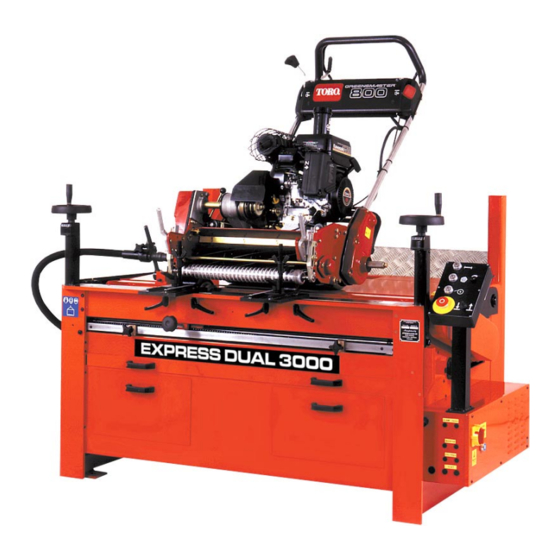
- Page 1 EXPRESS DUAL 3000 MANUAL EXPRESS DUAL 3000 ED3000 Automatic Spin Grinder User s Guide & ’ Instruction Manual Please read this manual carefully before using the Express Dual. This manual should be kept in a safe place so that it can be used for future reference.
- Page 2 EXPRESS DUAL ED3000 Precision Reel/Cylinder Grinder You are now the owner/operator of a Bernhard’s Express Dual 3000 which, if cared for and operated correctly, will give you years of good service. This manual will enable you to obtain the best results from your Express Dual so please read it thoroughly before using your machine.
- Page 3 TRAPPING FEET OR OTHER OBJECTS WHEN LOWERING LIFT PLATFORM BEWARE! HIGH VOLTAGE MAXIMUM GRINDSTONE DIAMETER 150mm MAXIMUM SPEED 2200 Rev/Min BEWARE! MOVING GRINDSTONE AND SHAFT REEL ROTATING AT BETWEEN 147 AND 255 Rev/Min TOTAL WEIGHT OF MACHINE (KG) © Bernhard and Company Limited...
- Page 4 LIFTING EYES BEWARE! MOVING COMPONENTS KEEP HANDS AND OTHER OBJECTS CLEAR WEAR EYE, EAR AND BREATHING PROTECTION TRAVERSE START CONTROL GRINDSTONE START CONTROL REEL START CONTROL STOP CONTROL ENGAGE / DISENGAGE (INCREASE / REDUCE) GRINDSTONE FEED © Bernhard and Company Limited...
- Page 5 EXPRESS DUAL • ED3000 Reel (Spin) Traverse On Grindstone Drive On Position Value Display Reset Display Balance Indicator Unclamp Clamp Emergency Stop (Twist to release) © Bernhard and Company Limited...
- Page 6 If a lift table is fitted NEVER attempt to lift in excess of the rated capacity, and always ensure that the area is clear before lowering the load. © Bernhard and Company Limited...
- Page 7 NOTE Ensure that the packing under the feet is correct before tightening the bolts, otherwise twisting of the frame may occur. © Bernhard and Company Limited...
- Page 8 The mainshaft should be washed down as instructed in the maintenance section of this manual. The feed control screws are normally coated with molycote, and may be washed down with WD40 if required and recoated with molycote (or similar anti friction coating) when dry. © Bernhard and Company Limited...
- Page 9 4. Identification of Tools and Equipment The items below may not necessarily be included since the tools and equipment supplied will vary according to the machine specification. Express Dual 3000 and 3000DX (see illustrated parts list). A4066 Long 1/2” AF Ball handled Allen Key A2706 3/16”...
- Page 10 The rear of the unit will be held by the radiused pressure bar at the rear of the grinder. © Bernhard and Company Limited...
- Page 11 The reel drive motor, traverse motor, and VSD inverter (reel spin speed control) are protected by individual fuses located in the electrical control box and accessible without the necessity of opening the box. © Bernhard and Company Limited...
- Page 12 A backing up plate is supplied to protect the rear of the units and to evenly disperse the force of the pressure bar across the width of the mower (see Fig. 6.2). © Bernhard and Company Limited...
- Page 13 “set up guide” should be completed and filed for future reference so that the identical multifix brackets positions can be used for all subsequent applications on the same type of unit. © Bernhard and Company Limited...
- Page 14 Should the reversing bar be dragged by the traverse assembly in the direction of travel during the grinding processes, causing the stone traverse to reverse prematurely, it will be necessary to adjust the reversing bar damper as indicated in the service bulletin (No.003). © Bernhard and Company Limited...
- Page 15 The drive head of the shaft can also be slid through it’s support for further adjustment or final connection/ disconnection of drive. 6.5.3 Tighten the drive rod via the allen screw in the flexible coupling onto the flat of the drive shaft. © Bernhard and Company Limited...
- Page 16 Go back to the right hand end and repeat the process and again release the contact only slightly. NOTE It is important that the grinding wheel should clear the highest blade along the full length of the reel before grinding commences. © Bernhard and Company Limited...
- Page 17 Repeat this process until the contact along the reel is even and parallel. 6.7.6 Screw in traverse knob to engage power traverse. NOTE Check auto traverse is changing direction at correct point at each end of its movement. © Bernhard and Company Limited...
- Page 18 Place hands on the left and right control wheels and move both hand wheels clockwise the same amount to apply an even cut. The Light Emitting Diode (LED) feed balance system fitted to the Express Dual 3000 spin grinding machine is designed to ensure that the operator has a simple visual indication that ensures that feed of cut is applied parallel across the length on any reel.
- Page 19 NOTE NEVER stop the machine while the grinding wheel and reel are in contact except in an emergency. Never allow the grinding wheel and reel to spark out. If this does happen put another cut on for a few more passes. © Bernhard and Company Limited...
- Page 20 This can best be done by detaching the motor drive and ensuring that the mechanism is moving freely. © Bernhard and Company Limited...
- Page 21 Place a wooden block under the mainshaft to the right hand side of the grinding wheel assembly, bridging the front bed and front channel to take the weight of the mainshaft when the side arm is removed (see Fig. 8.1.5). © Bernhard and Company Limited...
- Page 22 8.1.17 Apply more feed as necessary to true the stone. NOTE Dressing in this way should be carried out periodically to keep the ‘stone clean and true BUT remove only the minimum material off the stone to keep long service. © Bernhard and Company Limited...
- Page 23 NEVER grip the sleeve and nut assembly in a vice. Fully tighten the nut when the assembly is fitted to the mainshaft. Sleeve Mainshaft Remove minimal material from sides and bottom of key 2nd Key © Bernhard and Company Limited...
- Page 24 SMALL SHOT of grease should be applied annualy. These bearings run warm/hot, that IS OK. Extra grease will not reduce the temperature, more likely the reverse, the seals and subsequently the bearings may fail prematurely. © Bernhard and Company Limited...
- Page 25 MAINSHAFT MOUNTING AND MAIN MOTOR DRIVE _________ 28 TRAVERSE ASSEMBLY __________________________________ 30 REEL DRIVE ____________________________________________ 32 CLAMP ASSEMBLY ______________________________________ 34 MULTI-FIX BRACKET ASSEMBLY _________________________ 36 CONTROL BOX _________________________________________ 38 ELECTRICAL CABINET __________________________________ 39 GUARD ________________________________________________ 40 © Bernhard and Company Limited...
- Page 26 Dust Tray Handle..............2 A6111 Drawer Runner (Pad) .............. 4 A6742 Drawer Runner (Drawer) ............4 A6741 M5 x 10 Button Socket Screw ..........8 A5129 � �� � � � � � � �� � � �� © Bernhard and Company Limited...
- Page 27 Feed Nut............2 A4043 Spring Coupling Kit..........2 A9700 Encoder ............. 2 A8074 Saddle Clamp............ 2 A6851 M5 x 10 Button Head Screw......4 A5129 M5 Washer ............4 A5318 �� �� FEED ADJUSTMENT �� �� �� © Bernhard and Company Limited...
- Page 28 Washer M8 ................4 A5321 Motor Bolt Retaining Plate ............2 A4078 Hex. Set Screw M10 x 70 ............2 A5711 Locknut M10 ................2 A5503 Button Head Socket Screw M5 x 10 ........2 A5129 © Bernhard and Company Limited...
- Page 29 � �� �� MAINSHAFT MOUNTING AND MAIN MOTOR DRIVE � � �� �� �� �� �� �� � �� � �� �� � �� �� �� � �� �� �� � � ��...
- Page 30 Hex Head Screw M6 x 18............4 A5719 Washer M6 ................4 A5320 Capacitor 3uf for Traverse Motor ........... 1 A8148 Friction Spring for Reversing Bar..........1 A6746 Socket Screw 1⁄4”Whit x 1⁄4”............1 A5101 © Bernhard and Company Limited...
- Page 31 � � � � �� �� �� �� � �� � � �� �� �� � �� �� �� �� �� �� �� �� �� � �� �� �� �� �� �� �� �� �� �� �� TRAVERSE ASSEMBLY...
- Page 32 Socket Screw M6 x 12............. 1 A5146 Diamond Dresser ..............1 A6737 Locknut M10 ................1 A5503 Flexible Coupling..............1 A6744 Grub Screw 3/8” Whit x 3/8” ........... 2 A5106 Short Square Drive Shaft ............1 A4134 © Bernhard and Company Limited...
- Page 33 EXPRESS DUAL • ED3000 13 17 REEL DRIVE © Bernhard and Company Limited...
- Page 34 C’s’k Socket Screw M10 x 30 ..........4 A5117 Nut M10 ................... 4 A5503 Hex Head Bolt M10 x 45............2 A5706 Nyloc Nut M10 ................. 2 A5505 Washer M10 ................6 A5310 Pressure Plate (not shown) ............ 1 A6342 © Bernhard and Company Limited...
- Page 35 EXPRESS DUAL • ED3000 � � � � �� � � �� � �� CLAMP ASSEMBLY � � © Bernhard and Company Limited...
- Page 36 Cap Head Skt Screw M10 x 25 ..........4 A5116 Washer M12 ................4 A5315 Washer M10 ................4 A5310 Base Scale ................2 A6601 Button Head Skt Screw M4 x 8 ..........4 A5125 Multifix Channel (not shown)........... 2 A4087 © Bernhard and Company Limited...
- Page 37 �� � �� � �� �� �� �� � � � �� � �� �� � � �� MULTI-FIX BRACKET ASSEMBLY � �� �� ��...
- Page 38 (not with PIC) LED Light Green..............1 A8088 (not with PIC) PIC Control PCB ..............1 A8839 Lead for PIC Control PCB ............1 A8853 VIEW ON UNDERSIDE OF COVER CONTROLLER CONTROL BOX with PIC CONTROLLER © Bernhard and Company Limited...
- Page 39 Reset Button................1 A8130 Fuse Door................1 A6329 � � �� � � � ������� ����� ������ � � � � ��� ��� �� ��� �� �� �� �� ������� ����� ���� � �� �� © Bernhard and Company Limited...
- Page 40 Ball Pin for Gas Strut............... 4 A9281 Front Guard Gas Strut............. 2 A6731 Cap Head Screw M6 x 30 ............4 A5153 Plastic Rivet................32 A6758 Button Head Screw M6 x 10 ........... 2 A5142 © Bernhard and Company Limited...
- Page 41 EXPRESS DUAL • ED3000 Parts List (Continued) �� � � � � �� � �� � �� � � � GUARD �� �� �� © Bernhard and Company Limited...
- Page 42 Lift Table Lowering Solenoid 12v ..........1 A8391 Control Pendant 24v (not shown)..........1 A8018 Mains Control Pendant (not shown)........1 A8890 Label for Tail Lift Pendant (not shown) ........1 A6552 Mains Tail Lift Controller (not shown)........1 A8904 © Bernhard and Company Limited...
- Page 43 � � �� � �� �� � �� � � �� � �� � �� �� �� � �� �� �� �� �� � �� �� � �� �� �� �� LIFT TABLE � � © Bernhard and Company Limited...
- Page 44 10. Wiring Diagrams Microswitch L.H. SIDE ENCODER R.H. SIDE ENCODER BLACK BLUE CONTROL BOX BLACK Fuse #2 Com0 IMO G7 AC 100-240V Q00 Q01 Q02 SOCKET No.4 HOUR Com0 Com1 Com2 Q03 Com3 METER Fuse #1 MAINS SUPPLY Fuse #3 Traverse Motor Reel Drive Motor Main Motor...
- Page 45 10. Wiring Diagrams Microswitch R.H. SIDE ENCODER L.H. SIDE ENCODER BLACK BLACK BLUE CONTROL BOX Fuse #2 +485 -485 IMO G7 G7M-DR10A AC 100-240V SOCKET No.4 HOUR METER Com0 Com1 Com2 Com3 Fuse #1 MAINS SUPPLY Fuse #3 Traverse Motor WHITE Reel Drive Motor Main Motor...
- Page 46 10. Wiring Diagrams Microswitch L.H. SIDE ENCODER BROWN BLACK BLUE CONTROL BOX Fuse #2 IMO K10 MASTER Com2 Com3 SOCKET No.4 HOUR METER R.H. SIDE ENCODER Fuse #1 MAINS SUPPLY BLACK Fuse #3 Traverse Motor Reel Drive Motor Main Motor Reversing Contactor IMO K10 Traverse Contactor...
- Page 47 Wiring colours shown are for ease of wire tracing only and not actual wiring colours, except for the wires from the encoders which are shown as Fuse #6 actual colours and also written. MAINS SUPPLY EXPRESS DUAL 3000 WIRING DIAGRAM with PIC PCB...
- Page 48 If you have any service or operational problems contact your distributor, or phone our Technical Helpline (USA only) – 1-888 474 6348 (+44) 1788 811600 Bernhard and Company Ltd, England – or email techsupport@bernhard.co.uk use the technical support feedback form on our web site www.expressdual.com or www.bernhard.co.uk...
Need help?
Do you have a question about the Express Dual 3000 and is the answer not in the manual?
Questions and answers