Advertisement
Quick Links
Thank you for purchasing a HypnoCube kit. Instructions are online at www.hypnocube.com. Email any
questions to contact@hypnocube.com.
Parts List
The following parts make up the 8Square kit and should be in the box:
1. Shadowbox frame
2. Smoked acrylic panel
3. H8S printed circuit board (PCB)
4. Diffuse common-cathode RGB LED x67 (3 are spares)
5. 110VAC to 9VDC 300mA transformer (a.k.a. wall wart)
6. PIC18F4620 microcontroller (40 pins)
7. SN74AHC574 octal D-type flip-flop x4 (20 pins)
8. ULN2803A NPN Darlington transistor array (18 pins)
9. LM2574 5V switching regulator (8 pins)
10. 22 resistor array (16 pins)
11. 47 resistor array (16 pins)
12. 68 resistor array (16 pins)
13. 47K resistor x3 (yellow-violet-orange-gold)
14. 1K resistor x5 (brown-black-red-gold)
If you purchased the USB version of the kit, you will also get:
29. DLP-UB232R UART-USB bridge module
30. Mini-B USB cable
USB Features
If you have the USB interface, we provide a few sample programs to interface with your device and change
settings, play back your own animations, etc. Check around
and/or software for that.
Basic Button Commands
The two buttons are named A and B. "A"
denotes A button up, "a" denotes A button
down, etc., for sequences. See the online user
manual for more details.
Button(s) Down on
reset
Neither
Button A
Button B
Buttons A and B
Buttons A and B, hold
HypnoSquare Instructions v 1.3, May 2009
HYPNOCUBE
Things that go blink in the night
Effect
White screen
Blue screen
Green Screen
Red Screen
Red Screen, then
blinking, then Reset
Gadget
www.HypnoCube.com
Sequence
Description (Command name in bold)
while running
aA
Next visualization.
bB
Prev visualization.
abAB
Lock current visualization. Gadget shows a brief
pause then continues running the visualization.
Executing Next or Prev releases lock
baBA
Pauses current image, resulting in a still image.
Executing Next or Prev releases pause.
abBbBA
Removes currently playing visualization from the
playlist.
Visualization can be reinstated through the console
editor or through a Reset. Lock the visualization
prior to removal to prevent accidently removing
the wrong visualization.
- 1 -
15. 40 pin IC socket
16. 1N4148TR signal diode x24 (red)
17. 511-BAT48 rectifier diode (blue)
18. 330mH inductor
19. 0.1uF ceramic capacitor x5
20. 10uF electrolytic capacitor
21. 22uF electrolytic capacitor
22. 220uF electrolytic capacitor
23. 2.1mm DC power jack
24. Toggle switch
25. Momentary pushbutton x2
26. ¾" threaded standoff x4
27. ⅜" 4-40 screw x8
28. 32 pin header and 7 pin header (to be
spilt later)
to get the latest instructions
Advertisement

Related Manuals for Hypnocube HypnoSquare

Summary of Contents for Hypnocube HypnoSquare
- Page 1 HypnoSquare Instructions v 1.3, May 2009 HYPNOCUBE Things that go blink in the night Thank you for purchasing a HypnoCube kit. Instructions are online at www.hypnocube.com. Email any questions to contact@hypnocube.com. Parts List The following parts make up the 8Square kit and should be in the box: 1.
- Page 2 HypnoSquare Instructions v 1.3, May 2009 Introduction This is the first part of the instructions for building the 8×8 “8Square” kit. The three main parts are titled “The Good”, “The Bad” and “The Ugly”. “The Good” we will construct the controller board.
- Page 3 HypnoSquare Instructions v 1.3, May 2009 Part 1: The Good Part one is assembling the controller PCB. This should be straightforward for anyone who has done PCB work; there's nothing exotic here. Estimated completion time: 1 - 3 hours. We will start with the lowest-profile parts and work our way up, as that allows your working surface to hold the parts in place while we solder the bottom.
- Page 4 HypnoSquare Instructions v 1.3, May 2009 Note that for the blue diode the holes on the PCB are spaced a bit wider than the length of the diode, so you will want to bend the pins accordingly. The 24 signal diodes can have their pins bent against the body of the diode.
- Page 5 HypnoSquare Instructions v 1.3, May 2009 Step 4: Small capacitors Next solder the 5 small 0.1uf ceramic capacitors, shown in Figure 6, to the board in spots C4, C5, C6, C7, and C8. These are the decoupling caps for each IC.
- Page 6 HypnoSquare Instructions v 1.3, May 2009 Figure 10: SN74AHC574Ns in place. Next we will do the ULN2803A (Figure 9) and the LM2574 (Figure 11). Again, note the orientation – in particular, the LM2574 faces the opposite direction of the other ICs so it‟s easy to get wrong.
- Page 7 HypnoSquare Instructions v 1.3, May 2009 Figure 14: The PIC socket in place Step 7: Resistor arrays These are just an array of resistors packaged into a chip which we decided to use over discrete resistors for convenience. Note that the footprints on the PCB still show the individual resistors.
- Page 8 HypnoSquare Instructions v 1.3, May 2009 Step 8: Large capacitors and inductor There are 3 electrolytic capacitors to place. These are all orientation dependent - you will see a + symbol on the PCB for the positive wire, which is the longer of the capacitor leads. The negative lead is also marked on the body of the capacitor.
- Page 9 HypnoSquare Instructions v 1.3, May 2009 Step 9: Buttons There are two buttons to place above the capacitors and inductor. Note that the buttons have an interlocking set of nubs on their sides. Snap the two together, and insert as one into the PCB. Because the board won‟t lie flat with the buttons when turned upside down for soldering, first solder one pin on each buttons and ensure that the buttons are completely seated before soldering the other pins.
- Page 10 HypnoSquare Instructions v 1.3, May 2009 Part 2: The Bad In "The Bad" we will solder all of the LEDs into place. Admittedly this isn‟t so bad, but the 4-pin LEDs with their tight pitch can be quite a bit trickier to solder than you might expect. And there are a lot of them to do! Estimated completion time: 1 - 3 hours.
- Page 11 HypnoSquare Instructions v 1.3, May 2009 Figure 27: A row of LEDs ready to be soldered. Note the lead lengths. Chances are you will bridge some of the LED pins with solder. I‟ve done a dozen or so in prototypes and early builds, and I still get one or two per board.
- Page 12 HypnoSquare Instructions v 1.3, May 2009 Part 3: The Ugly In “The Ugly” we will put everything together – the remaining power bits, connecting the LED board to the controller board, and putting the whole enchilada into the shadow box.
- Page 13 HypnoSquare Instructions v 1.3, May 2009 Next place the controller board on top, lining up the header pins to their spots on the controller board. Secure the headers into place by soldering one pin on each one to the controller board, and then flip over and do the same to the sockets on the LED board.
- Page 14 HypnoSquare Instructions v 1.3, May 2009 Figure 34: Power jack in place. Step 3 (Optional): The USB Module If you bought the kit with the USB module, we will attach it now. Otherwise, you can skip to the next step.
-
Page 15: Step 4: The Power Switch
HypnoSquare Instructions v 1.3, May 2009 Because the module does not lie flat when placed upside down for soldering, it can be difficult to mount straight on the first try. Solder just one corner pin and make sure that it is level and seated all the way before doing the rest. - Page 16 HypnoSquare Instructions v 1.3, May 2009 Figure 38: Power switch in place. Step 5: Test! Now that you‟ve got power in place, you can test everything out. Plug the controller in to the LED board, plug the power cord in, and throw the switch.
- Page 17 HypnoSquare Instructions v 1.3, May 2009 Figure 40: PCB with standoffs. I recommend plugging in the power plug (and USB cable if applicable/desired) at this point because it‟s about to get less accessible. Next, place the back panel from the frame over the controller board, aligning it so the buttons and power switch are accessible through the slot cut into the panel, and screw it down using the remaining screws.
-
Page 18: Step 7: Final Assembly
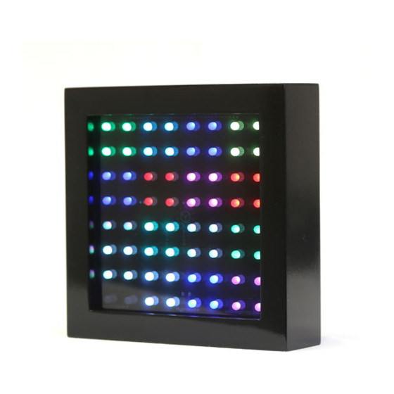
HypnoSquare Instructions v 1.3, May 2009 Step 7: Final Assembly Before you assemble the square into its final glorious form, you need to make a decision: clear or smoked? We like the smoked acrylic front, but you can go with the original glass if you prefer. Of course you can try them both and compare them yourself. - Page 19 HypnoSquare Instructions v 1.3, May 2009 Figure 44: The finished square (with acrylic front.) - 19 -...
-
Page 20: Appendix 1: Troubleshooting
We released detailed specs on the protocol to talk to the PIC, sample C++ source code, and a sample program to fiddle with the HypnoCube settings. But for those who really want to get their hands dirty and reprogram the PIC microcontroller with their own code, here are some things to get you started. - Page 21 HypnoSquare Instructions v 1.3, May 2009 If you might be swapping the PIC out a lot, we recommend the use of a ZIF (zero insertion force) socket. We have found that the Aries Series 526 low profile ZIF socket works well.
Need help?
Do you have a question about the HypnoSquare and is the answer not in the manual?
Questions and answers