Table of Contents
Advertisement
Quick Links
Advertisement
Table of Contents

Related Manuals for FireFlex Systems Inc. ICAF System

Summary of Contents for FireFlex Systems Inc. ICAF System
- Page 1 Operation & Maintenance Manual FM-0723-0-02 A...
- Page 2 Integrated Compressed Air Foam System with Electric Failsafe Release Owner's Operation and Maintenance Manual FM-0723-0-5B...
- Page 3 & M WNER PERATION AINTENANCE ANUAL ICAF - Integrated Compressed Air Foam System FireFlex Systems Inc. 1935 Lionel-Bertrand Blvd Boisbriand, QC (Canada) J7H 1N8 Tel: (450) 437-3473 Toll free: (866) 347-3353 Fax: (450) 437-1930 info@fireflex.com Web Site: http://www.fireflex.com - E-Mail: FM-0723-0-5B...
-
Page 4: Table Of Contents
& M WNER PERATION AINTENANCE ANUAL ICAF - Integrated Compressed Air Foam System Table of contents ICAF C OMPRESSED YSTEM WITH LECTRIC AILSAFE ELEASE ARC-1 C ONTROL ANEL Description Form N General Section .......................... FM-0723-0-07 1. Applicable standards 2. Listings & Approvals 3. - Page 5 WNER PERATION AINTENANCE ANUAL ICAF - Integrated Compressed Air Foam System Table of contents (cont'd) ICAF System Trim Schematic ....................FM-0723-0-10 1. Description 2. Normal condition Trim schematic Trim components Air Supply Section ........................FM-0723-0-12 1. Design & selection 2. Interconnection piping to ICAF system 3.
- Page 6 & M WNER PERATION AINTENANCE ANUAL ICAF - Integrated Compressed Air Foam System FireFlex Systems Inc Copyright © 2004-2009 All Rights Reserved Reproduction or use, without express written permission from FireFlex Systems Inc, of any portion of this manual is prohibited. While all reasonable efforts have been taken in the preparation of this manual to assure its accuracy, FireFlex Systems Inc assumes no liability resulting from any errors or omissions in this manual, or from the use of the information contained herein.
- Page 7 & M WNER PERATION AINTENANCE ANUAL ICAF - Integrated Compressed Air Foam System FM-0723-0-5B...
-
Page 8: General Section
It is used as a reference to maintain records in our computerized data base. Have these serial numbers The ICAF system shall be installed in a dry and clean handy when calling for information on your unit. location. Verify that all equipment is properly heated and protected to prevent freezing and physical damage. -
Page 9: Configuration Description
The connection is used to supply compressed air between required to supply the nozzles in the hazard(s). the cylinders bank and the ICAF system. The piping is factory prepared according to installation arrangement and is supplied with the system. The system can be configured for:... -
Page 10: Release Systems
System actuation, manual or automatic, will cause the control of the ICAF system unit or by external air supply. It is panel to go into alarm and water flow conditions. -
Page 11: Installation
Foam the ICAF system is in good operating condition and that it concentrates are subject to freezing or deterioration from functions as intended. Components shall be restored to full prolonged storage at high temperatures, the system shall operational condition following inspection and testing. - Page 12 (if available) and with the most recent Drainage: test results. The area beneath and surrounding a ICAF system shall be The following requirements are based upon NFPA-25. inspected to ensure that drainage facilities, such as trap sumps and drainage trenches, are not blocked and retention Monthly: embankments or dikes are in good repair.
- Page 13 The test procedures shall simulate anticipated emergency events so the response of the ICAF system can be Low points in the ICAF system shall be drained after each evaluated. operation. Protection shall be provided for any devices or equipment Records indicating the date the ICAF system was last tripped subject to damage by system discharge during tests.
-
Page 14: User Interface
Page 1 of 6 ICAF - Integrated Compressed Air Foam System Control Panel Section User Interface Section visible through Alpha-Numeric Display the door window Partial Acknowledge AC Power Alarm Disable System LED System Status LEDs Audibles Alarm Silence Supervisory Release Indicators Silence / Activate... -
Page 15: Keyboard - System Main Control Keys
Page 2 of 6 ICAF - Integrated Compressed Air Foam System Control Panel Section Under normal conditions, pressing on the SYSTEM RESET 3. Keyboard - System main control keys key make the local sounder beep once and will also Panel is provided with a membrane type keyboard as shown perform a LAMP TEST function. - Page 16 Page 3 of 6 ICAF - Integrated Compressed Air Foam System Control Panel Section The bottom section's GROUND FAULT STATUS indication is for technician use and displays factory codes on Ground Fault condition for troubleshooting purposes. Refer to TROUBLESHOOTING section for additional details. In the TIMER STATUS screen, all the set values of the various timers are displayed as shown in the example below (actual screen may differ depending on system...
-
Page 17: Local Alphanumeric Display
Page 4 of 6 ICAF - Integrated Compressed Air Foam System Control Panel Section The start-up procedure should last only a few seconds, INSPECTION LOG is used in conjunction with the after which, if the system is back under normal condition, ARC-1 PC Interface software. - Page 18 Page 5 of 6 ICAF - Integrated Compressed Air Foam System Control Panel Section Here is a simulated SYSTEM EVENT screen illustrating the Next is the technical section, displaying various data for various displays: the highlighted event: TYPE is a three letter code displaying which type of event is highlighted where: ALM = Alarm TBL = Trouble...
- Page 19 Page 6 of 6 ICAF - Integrated Compressed Air Foam System Control Panel Section This page is left intentionally blank FM-0723-0-26B...
-
Page 20: System Sequence Of Operation
Page 1 of 2 ICAF - Integrated Compressed Air Foam System Sequence of Operation System Sequence of Operation System Output Activation: IMPORTANT NOTICE ! The detailed sequence of operation - the ALARM signalling circuit will be activated, described below is specifically written for your application. - the release circuit will be activated and the CAF Other system's operation may differ greatly depending on discharge will occur,... - Page 21 Integrated Compressed Air Foam System Sequence of Operation Emergency Discharge Shut-Off Because the ICAF System cannot be turned off by the Warning ! DO NOT CLOSE THE WATER SUPPLY TO operation of a single valve as is the case for a standard MAKE REPAIRS WITHOUT PLACING A FIRE PATROL sprinkler system, a manual shut-off function is provided.
- Page 22 Page 1 of 2 ICAF - Integrated Compressed Air Foam System System Wiring System Wiring The following is a detail of the modules provided in this unit and their placement location, followed by the wiring diagrams for each of these modules. ARC-1 System Modules Placement Detail Power Supply &...
- Page 23 Page 2 of 2 ICAF - Integrated Compressed Air Foam System System Wiring SSA Module – System Supervisory Circuits ARA Modules – Auxiliary Relay Outputs SLOT SLOT [V+] 1 [C] 1 7 [C] "R1" ALARM "R3" [NO] 2 RS485 SERIAL [V-] 2 DISCHARGE PORT CONNECTION...
-
Page 24: Description
Green LAMP for power is activated in continuous 1. Description manner. The ICAF System utilizes a Flow Control valve (B14) to b) All other LAMPS are deactivated. control water flow into system piping equipped with open c) Alpha-numeric Display shows default screen rotating spray nozzles. -
Page 25: Trim Schematic
Page 2 of 4 ICAF - Integrated Compressed Air Foam System System Trim Section Trim Schematic: System with electric fail-safe release FM-0723-0-10 A... -
Page 26: Trim Components
Page 3 of 4 ICAF - Integrated Compressed Air Foam System System Trim Section Trim Components: C. CAF MIXING CHAMBER: A. AIR SUPPLY: C1 Mixing chamber A1 Air pneumatically operated control valve (N.C.) C2 Foam injector A2 Safety valve C3 Air injector A3 System flushing valve C4 Water injector A4 Air supply pressure gauge &... - Page 27 Page 4 of 4 ICAF - Integrated Compressed Air Foam System System Trim Section FM-0723-0-10 A...
-
Page 28: Air Supply Section
Integrated Compressed Air Foam System Air Supply Section Air supply section 2. Interconnection Piping to ICAF System Compressed Air Foam is composed of 90% compressed air. There is one interconnection line (circled item 4) provided on This air is provided by DOT and TC certified compressed air all air cylinders banks. -
Page 29: Operation
Open the high pressure isolation valve (V10). and the ICAF System air supply line (circled item 4). Once the maximum pressure is attained on the high If there is no leak, pressure will build up in the pressure gauge (V6), close the high pressure manifold and the piping. - Page 30 Page 3 of 4 ICAF - Integrated Compressed Air Foam System Air Supply Section Figure 2 – Compressed Air Cylinders Bank (Rack mounted) Air supply Components: Cylinders rack Pressure gauge Compressed air cylinder Pressure transducer Safety release disk High pressure manifold Cylinder valve Refilling outlet Pressure regulator...
- Page 31 Page 4 of 4 ICAF - Integrated Compressed Air Foam System Air Supply Section This page is left blank intentionally. FM-0723-0-12F...
-
Page 32: Foam Supply Section
Foam tank normal conditions Hydrocarbons Before placing the foam tank in service, verify that the piping Ansul Ansulite 3X3 LV between the foam tank and the ICAF System is properly Polar Solvents installed and secured. Ansul Ansulite 3X3 LV 1. Tank foam refill valve (T3) is locked CLOSED. -
Page 33: Filling Procedure
Page 2 of 4 ICAF - Integrated Compressed Air Foam System Foam Supply Section 4. Check the sight gauge (T5) level: 3. Foam refill valve (T3) and both level sight gauge a) If level is normal, CLOSE the bottom sight gauge isolation valves (T4) should be closed. - Page 34 Sight gauge (T5) should not show any 1. System's air supply should be open; air pressure reading. gauge (A4) inside the ICAF System cabinet should 1. Verify that foam storage tank pressure gauge (T7) indicate a pressure of about 100 psi (689 kPa).
- Page 35 Page 4 of 4 ICAF - Integrated Compressed Air Foam System Foam Supply Section Figure 1 – Foam storage tank schematic Foam storage tank components T1 Foam storage tank T6 Vent valve T2 Dip tube T7 Pressure gauge T3 Storage tank drain valve / Foam refill valve T8 Pressure safety valve T4 Level sight gauge isolation valves T9 Vent valve...
-
Page 36: System Characteristics Section
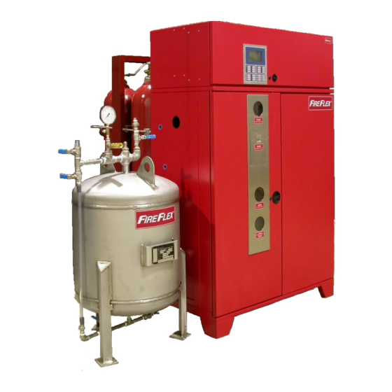
Page 1 of 4 ICAF - Integrated Compressed Air Foam System System Characteristics Section Cabinet for Self-Contained Unit (With Control Panel) The ICAF unit cabinet is made of sturdy 14 gauge steel, measuring 36" x 20" x 71" (91,4 x 50,8 x 180,3 cm) or 46" x 24"... - Page 37 Page 2 of 4 ICAF - Integrated Compressed Air Foam System System Characteristics Section Figure 1 – Dimensions: 2" MAX. See Note 9/16" DIA. (4 HOLES) FM-061H-0-22A FLOOR ANCHORING TEMPLATE Cabinet Small 36" 20" 57" 14" 4" 2¾" 4" Large 46"...
- Page 38 Page 3 of 4 ICAF - Integrated Compressed Air Foam System System Characteristics Section Drilling Guide: Wiring Routing: When drilling in the cabinet to install wiring conduits or pipes, Wiring shown in Figure 3 below indicates typical Wiring use only the shaded area shown below. Always avoid drilling Routing for Power Limited Circuits.
- Page 39 Page 4 of 4 ICAF - Integrated Compressed Air Foam System System Characteristics Section This page is left blank intentionally. FM-0723-0-14C...
- Page 40 Page 1 of 2 ICAF - Integrated Compressed Air Foam System Limited Warranty Limited Warranty FireFlex Systems inc. (known herein as "the Manufacturer") The Manufacturer shall not be liable for any personal injury warrants to its customer that its products shall be free of which may arise in the course of or as a result of the use of defects in material [or part(s)] and workmanship for a period the manufacturer's products.
- Page 41 Page 2 of 2 ICAF - Integrated Compressed Air Foam System User Notes User Notes FM-0723-0-16D...
Need help?
Do you have a question about the ICAF System and is the answer not in the manual?
Questions and answers