Table of Contents
Advertisement
Quick Links
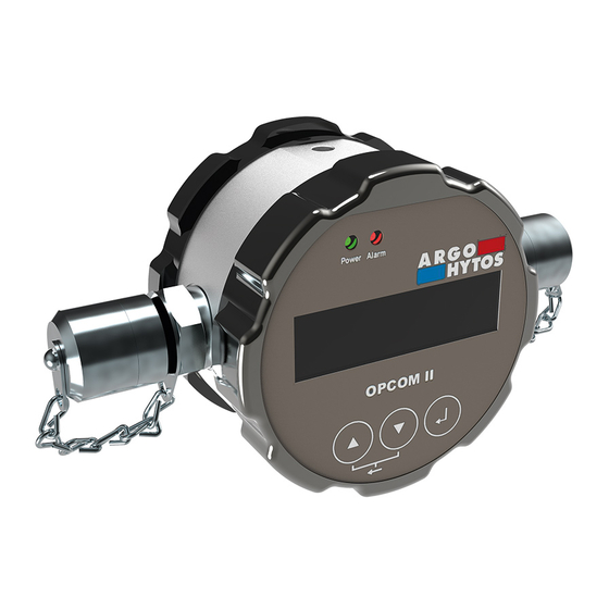
Operating Manual
OPCom Particle Monitor
SPCO 300-1000 / 2000 / 1200
www.argo-hytos.com
Subject to change · V 2.02.20 · EN
Safety and operating instructions
Read safety and operating instructions before use.
Note:
The indicated data only serve to describe the product.
Information regarding the use of this product are only examples and suggestions.
Catalog specifications are no guaranteed features.
The information given does not release the user from his / her own assessments and inspections.
Our products are subject to a process of natural wear and aging.
© All rights are reserved by ARGO-HYTOS GMBH, even in the event of industrial property rights.
Any right of disposal such as copying and distribution rights shall remain with us.
The picture on the title page shows a configuration example. The delivered product may thus differ
from the illustration.
Original instruction
Page 1
Advertisement
Table of Contents

Related Manuals for Argo-Hytos OPCom

Summary of Contents for Argo-Hytos OPCom
- Page 1 Our products are subject to a process of natural wear and aging. © All rights are reserved by ARGO-HYTOS GMBH, even in the event of industrial property rights. Any right of disposal such as copying and distribution rights shall remain with us.
-
Page 2: Table Of Contents
OPCom Contents Contents ..................................2 About this documentation ............................5 Applicability of this documentation ..........................5 Required and supplementary documentation .......................5 Presentation of information ............................5 1.3.1 Safety instructions ..............................5 1.3.2 Symbols ..................................6 1.3.3 Terms ...................................6 1.3.4 Abbreviations ................................6 Safety instructions ..............................7 About this chapter ...............................7 Intended use ................................7... - Page 3 CANopen Communication Objects ..........................43 16.1.3 Service Data Object (SDO) ............................44 16.1.4 Process Data Object (PDO) ............................46 16.1.5 PDO Mapping ................................46 16.1.6 „CANopen Object Dictionary“ in detail ........................48 16.2 CAN J1939 ................................53 Page 3 www.argo-hytos.com Subject to change · V 2.02.20 · EN...
- Page 4 FAQ ..................................62 Technical data ................................64 23.1 Technical data ................................64 23.2 Dimensional drawing ..............................65 Appendix .................................66 24.1 Cable lengths ................................66 24.2 Coding of error bits ..............................66 24.3 Particle contaminations ..............................68 Page 4 www.argo-hytos.com Subject to change · V 2.02.20 · EN...
-
Page 5: About This Documentation
This documentation is applicable for the following products: › OPCom Particle Monitor › OPCom Particle Monitor Phosphate Ester › OPCom Particle Monitor without display This documentation is written for service engineers, technicians, operators and system operators. This document contains important information for safe and appropriate assembly, transport, activation, operation, usage, servicing, dismantling and simple troubleshooting. -
Page 6: Symbols
Size specification for particles when using ISO-MTD Table 4: Terms 1.3.4 Abbreviations Abbreviation Meaning Ordinal number Automatic particle counter Medium test dust Double-digit indication of minutes Double-digit indication of seconds Table 5: Abbreviations Page 6 www.argo-hytos.com Subject to change · V 2.02.20 · EN... -
Page 7: Safety Instructions
(functional safety). ARGO-HYTOS GmbH assumes no liability for damages resulting from improper use. The risks associated with improper use are solely with the user. -
Page 8: General Safety Instructions
Product and technology related safety instructions CAUTION Laser The OPCom Particle Monitor contains a laser sensor that is classified for intended use as a class 1 laser according to DIN EN 60825-1:2001-11. In reasonably foreseeable circumstances, the accessible laser radiation is not dangerous. ... - Page 9 On the side of the device, between a Minimess connection and the connector for the sensor cable, a label indicates the laser radiation. Fig. 2: Label laser radiation Page 9 www.argo-hytos.com Subject to change · V 2.02.20 · EN...
-
Page 10: General Instructions
CAUTION Danger due to improper handling! Material damage! The OPCom Particle Monitor may only be used in accordance with Section 2-2, “Intended use”. Leakage or spillage of hydraulic fluid! Environmental pollution and ground water pollution! Use oil binding agents in order to bind leaked hydraulic oil. -
Page 11: Scope Of Delivery
4. Scope of delivery The package includes: › 1 OPCom Particle Monitor › 1 Quick Start Guide Page 11 www.argo-hytos.com Subject to change · V 2.02.20 · EN... -
Page 12: About This Product
The larger the particle, the greater the reduction in intensity. The OPCom Particle Monitor allows users to monitor the contamination level and the trend regarding cleanliness of fluids. Differen- ces in absolute precision may arise compared to particle counters calibrated according to ISO 11171:99. However, the deviation is less than one scale number. -
Page 13: Component Overview
In case of a jump to the higher level before pressing the selection button, the changes will not be saved. Identification of the product Fig. 5: Nameplate Page 13 www.argo-hytos.com Subject to change · V 2.02.20 · EN... -
Page 14: Transport And Storage
There are no special transport instructions for this product. However, observe the instructions in Chapter 2, “Safety instructions”. For storage and transport, observe the specified environmental conditions stated in the technical data. Page 14 www.argo-hytos.com Subject to change · V 2.02.20 · EN... -
Page 15: Assembly
The device should be installed at a relevant measurement location in the hydraulic circuit where constant pressure conditions exist. The pressure may vary, but it must not show any peaks or strong fluctuations during the measurement. Page 15 www.argo-hytos.com Subject to change · V 2.02.20 · EN... -
Page 16: Mounting
Screw depth Bottom 4 x M5 Max. 4 Nm (strength class 8.8) Min. 5 Laterally 2 x M6 Max. 8 Nm (strength class 8.8) Min. 6 Table 6: Mounting options Page 16 www.argo-hytos.com Subject to change · V 2.02.20 · EN... -
Page 17: Mechanical Stress
Max. vibration in all three axes 5 ...9 Hz Amplitude: +/-15 mm 9 ...16,5 Hz 16,5 ...200 Hz 10 g Table 7: Permitted mechanical stress Fig. 9: Inadmissible mechanical stress Page 17 www.argo-hytos.com Subject to change · V 2.02.20 · EN... -
Page 18: Electrical Connection
The sensor cable must be shielded. To achieve IP67 degree of protection, only suitable connectors and cables must be used. The tightening torque for the connector is 0.1 Nm. Page 18 www.argo-hytos.com Subject to change · V 2.02.20 · EN... -
Page 19: Commissioning
The information for intended use, the operating conditions and the technical specifications must be adhered to. Attach the particle monitor according to chapter 7 "Assembly". Cables and hoses must be outside of the movement range of the operating personnel (tripping hazard). Page 19 www.argo-hytos.com Subject to change · V 2.02.20 · EN... -
Page 20: Start Screen
According to ISO 4406 the ordinal number for the 21 µm measuring channel is not evaluated. This measured value is, however, shown as additional information and indicated by a reduced size. Page 20 www.argo-hytos.com Subject to change · V 2.02.20 · EN... -
Page 21: Menu And Operation
Select the number to change, and change it using the arrow keys [] and []. The changes are only accepted once you confirm using [ ] after the last position. If you jump to a higher level before final confirmation, the changes will be rejected. Page 21 www.argo-hytos.com Subject to change · V 2.02.20 · EN... -
Page 22: Menu Structure
11.1 Menu structure Fig. 13: Menu structure Page 22 www.argo-hytos.com Subject to change · V 2.02.20 · EN... -
Page 23: Operating Modes
(according to ISO 4406:17), the measuring time should be at least 120 seconds. Standard setting for the measuring time is 60 seconds. 11.2.1 Time-controlled measurement The OPCom Particle Monitor works with the set measuring time and pause times between measurements. The following settings are to be observed: Parameter Min. -
Page 24: Automatic
OZ 14 µm ≥ limit value OZ 21 µm ≥ limit value NAS 1638 00, 0, 1, 2...12 OZ ≥ limit value GOST 17216 00, 0, 1, 2...17 Table 11: Alarm configuration standard Page 24 www.argo-hytos.com Subject to change · V 2.02.20 · EN... -
Page 25: Filter Mode
In a hydraulic system short-term increases in concentration (peaks) may arise, which are not representative for the overall system, e.g. by operating a manual valve. The OPCom detects these changes and displays them correctly. The low-pass filter ensures that when an alarm is set according to chapter 12.3.1.1 and 12.3.1.2, it is not triggered at each peak. -
Page 26: Configuration Analog
Output independent from the set standard. ISO, SAE and NAS can be shown on GOST 17216 the display, GOST is however issued via the analog current output. Table 14: Configuration of the analog current output Page 26 www.argo-hytos.com Subject to change · V 2.02.20 · EN... -
Page 27: Standard
Configuration flow 11.6.1 Automatic In addition to the particle size and number of particles, the OPCom Particle Monitor also calculates a volume flow index to be able to evaluate the particle concentration. The calculated flow rate index is not an exact measurement of the volume flow. It is an internal calculation value, which may be used as an indicator during installation and commissioning of the unit. -
Page 28: Baud Rate Can
The transmitted data string corresponds to the response to the command “RVal”. For further information see chapter 16.2 "Read commands". Example for a data string: $Time:78.8916[h];ISO4um:0[-];ISO6um:0[-];ISO14um:0[-];ISO21um:0[-];SAE4um:000[-]; SAE6um:000[-];SAE14um:000[-];SAE21um:000[-];NAS:00[-];GOST:00[-];Conc4um:0.00[p/ml]; Conc6um:0.00[p/ml];Conc14um:0.00[p/ml];Conc21um:0.00[p/ml]; FIndex:50000[-];MTime:60[s]; ERC1:0x0000;ERC2:0x0000;ERC3:0x0000;ERC4:0x0800;CRC:Ä Page 28 www.argo-hytos.com Subject to change · V 2.02.20 · EN... -
Page 29: Configuration Display
See chapter 21. › Temperature: Internal electronics temperature. The displayed value does not directly correspond to the temperature of the oil. › Reinforcement: Adjusted amount for the internal detector. Page 29 www.argo-hytos.com Subject to change · V 2.02.20 · EN... -
Page 30: Operating Hours
11.10.4 Error info The OPCom Particle Monitor collects various errors, information and operating status and summarizes them into four 16 bit values, the ERC (Error Code). These are always shown in hexadecimal notation. For further information on the decoding see Chapter 25.2 "Coding of error bits". -
Page 31: Calibration
NECESSARY Fig. 18: Display message calibration note Resetting the calibration note on the display can only be carried out by ARGO-HYTOS service. The remaining hours until the appearance of the first message can be retrieved in the device menu under "SENSORPARAM >... -
Page 32: Analog Current Output (4
The analog current output gives a signal from 4 to 20 mA. Below, the conversions to the respective ordinal number are described. l/mA ISO 4406:17 SAE AS 4059E Table 16: Comparison table current output to ordinal number ISO and SAE Page 32 www.argo-hytos.com Subject to change · V 2.02.20 · EN... -
Page 33: Sequential Data Output For Iso 4406:17 And Sae As 4059E
Each sequence starts with a 20 mA signal for 4 seconds. The following figure shows a complete output sequence with the start character. For NAS and GOST no sequential output is available. 2 sec. Time / s Fig. 21: Sequential data output Page 33 www.argo-hytos.com Subject to change · V 2.02.20 · EN... -
Page 34: Switching Inputs And Outputs
1 (L+) and pin 2 (L-). Missing (false) Pin 7 is not connected = L+ Alarm (floating). R = 1...10KΩ R ≥100Ω Table 19: Switching behavior of switching output option 1 Page 34 www.argo-hytos.com Subject to change · V 2.02.20 · EN... -
Page 35: Option 2
= 0,5A Missing (false) Pin 7 is not connected = L- = 0V Alarm (floating). = 4 W = 0,5A Table 20: Switching behavior of switching output option 2 Page 35 www.argo-hytos.com Subject to change · V 2.02.20 · EN... -
Page 36: Communication Rs232
15. Communication RS232 The OPCom Particle Monitor has a serial interface, via which it can be read out and configured. For this purpose, a PC and an appropriate terminal program or a readout software is needed. The sensor has to be connected to a free COM port of a computer. - Page 37 Deletion usually takes a few seconds. The end is marked by “finished“. Table 21: RS232 Read commands [CR] = Carriage Return [LF] = Line Feed %d / %c / %f = Place holder Page 37 www.argo-hytos.com Subject to change · V 2.02.20 · EN...
-
Page 38: Configuration Commands
Limit value alarm ISO/SAE 4µm (depending on set standard) Write WAlarm4%c[CR] ISO: %c = 0…28 Alarm4:%c[-];CRC:z[CR][LF] 0 = Alarm deactivated Default: 0 SAE: %c = 000…12 000 = Alarm deactivated Default: 000 Read RAlarm4[CR] Page 38 www.argo-hytos.com Subject to change · V 2.02.20 · EN... - Page 39 %d = 3: ISO/SAE 14μm %d = 4: ISO/SAE 21μm %d = 5: ISO/SAE sequential (default) %d = 6: NAS %d = 7: GOST Read RCon[CR] See answer: „RCon“ Page 39 www.argo-hytos.com Subject to change · V 2.02.20 · EN...
- Page 40 0 = to be sent on value change Default: 10 Read RCJInt[CR] Table 22: RS232 Configuration commands [CR] = Carriage Return [LF] = Line Feed %d / %c / %f = Place holder Page 40 www.argo-hytos.com Subject to change · V 2.02.20 · EN...
-
Page 41: Checksum Calculation (Crc)
The decimal value of each character sent in a string (see ASCII-table) has to be added up. Including Line feed [LF] and Carriage Return [CR]. If the result is dividable through 256, the transmission is error-free. An example of the response of the OPCom to the command „RMemS[CR]“ is shown below. (Reading out the memory usage) „RMemS[CR]“... -
Page 42: Communication Can
8 Byte user data Data Length Code End of message Address, service type (PDO, SDO, etc.) Receiver sets bit to „Low“ Start of message Cyclic Redundancy Checksum Fig. 25: CANopen message format Page 42 www.argo-hytos.com Subject to change · V 2.02.20 · EN... -
Page 43: Canopen Object Dictionary" In General
Wait for boot-up or heartbeat from the sensor Configuration of sensors and communication parameters via SDO NMT to all nodes / to sensor in order to enter operational mode Fig. 26: CANopen Bus initialization process Page 43 www.argo-hytos.com Subject to change · V 2.02.20 · EN... -
Page 44: Service Data Object (Sdo)
Please consult "CiA Draft Standard 301" for the exact specifications of the SDO protocol. CAN Message user data CAN-ID CANopen COB-ID 11 Bit Index Sub-index CANopen SDO Message user data Table 28: Setup of a SDO message Page 44 www.argo-hytos.com Subject to change · V 2.02.20 · EN... - Page 45 COB-ID 11 Bit Message from 0x580 + 0x08 0x60 0x17 0x10 0x00 0x00 0x00 0x00 0x00 client to sensor NodelD Table 32: SDO upload response from the server to the client Page 45 www.argo-hytos.com Subject to change · V 2.02.20 · EN...
-
Page 46: Process Data Object (Pdo)
COB-ID and possibly the event timer. The communication parameters for the TPDOs 1 to 4 are documented in OD at the index 0x1800 to 0x1803. Byte Index (16 Bit) Sub-index (8 Bit) Object length in Bit (8 Bit) Fig. 29: Basic structure of a PDO mapping entry Page 46 www.argo-hytos.com Subject to change · V 2.02.20 · EN... - Page 47 The sensor supports certain types of TPDO (see table 33), which can be inserted for the respective communication parameters of the TPDOs (see Fig. 30). Type supported cyclically not cyclically synchronously asynchronously 1-240 241-253 Table 33: Description of TPDO types Page 47 www.argo-hytos.com Subject to change · V 2.02.20 · EN...
-
Page 48: Canopen Object Dictionary" In Detail
The complete object dictionary is represented in the following table. With few exceptions, the possible settings correspond to the CANopen Standard as described in DS 301. Suitable EDS files for the sensors are available on the homepage of ARGO-HYTOS GMBH. mapped on... - Page 49 PDO mapping for 5th unsigned 32 20020408h SAE21µm, 1 Byte im app obj. to be 2002h, sub 04 mapped TPDO3 mapping 1A02h record parameter number of entries unsigned 8 largest sub index Page 49 www.argo-hytos.com Subject to change · V 2.02.20 · EN...
- Page 50 000, 00 and 0, valid for all classes 0 == SAE 000 1 == SAE 00 2 == SAE 0 3 == SAE 1 … 14 == SAE 12 (maximum value) Page 50 www.argo-hytos.com Subject to change · V 2.02.20 · EN...
- Page 51 0 == NAS 00 1 == NAS 0 2 == NAS 1 … 13 == NAS 12 (maxi- mum value) 2007h GOST measurement record number of entries unsigned 8 largest sub index Page 51 www.argo-hytos.com Subject to change · V 2.02.20 · EN...
- Page 52 0 = ISO 1 = SAE 2 = NAS 3 = GOST alarm type unsigned 16 0 = standard alarm 1 = filter mode Page 52 www.argo-hytos.com Subject to change · V 2.02.20 · EN...
-
Page 53: Can J1939
Size of the record will be sent back on reading Table 34: Communication-related object dictionary 16.2 CAN J1939 For further information see www.argo-hytos.com Function available only from software version 2.00.15. Page 53 www.argo-hytos.com Subject to change · V 2.02.20 · EN... -
Page 54: Classification Systems
17. Classification systems The automatic particle counter (APC). which is used for the calibration of the OPCom particle monitor is primary calibrated according to ISO 11171. The ordinal numbers of the OPCom particle monitor are displayed according to ISO 4406. these are determined by the measured particle concentration for 4. -
Page 55: Cleanliness Classes According To Sae As 4059E
Concentration in particles / ml ISO 4406:17 Display OPCom From up to and including 10.00 20.00 5.00 10.00 2.50 5.00 1.30 2.50 0.64 1.30 ≤ 6 0.32 0.64 ≤ 6 0.16 0.32 ≤ 6 0.08 0.16 ≤ 6 0.04 0.08 ≤... -
Page 56: Cleanliness Classes According To Nas 1638
The NAS 1638 is divided into different size classes. 5-15µm, 15-25µm, 25-50µm, … The particles are counted differentially and not accumulated as in ISO 4406. The OPCom can only measure the sizes 4, 6, 14, 21 µm. Therefore, the cleanliness class is calculated only based on NAS 1638. -
Page 57: Cleanliness Classes According To Gost 17216
The GOST 17216 is divided into different size classes. 5-15µm, 15-25µm, 25-50µm, … The particles are counted differentially and not accumulated as in ISO 4406 The OPCom can only measure the sizes 4, 6, 14, 21 µm. Therefore, the cleanliness class is calculated only based on GOST 17216. -
Page 58: Maintenance And Repair
Do not use a high-pressure cleaner for cleaning. Close all openings with suitable protective caps / devices. Check that all seals and caps of the plug-in connections are secure, so that no humidity can penetrate into the OPCom Particle Monitor. -
Page 59: Decommissioning, Disassembly, Disposal
19. Decommissioning, disassembly, disposal The OPCom particle monitor is a component which does not have to be taken out of operation. Therefore, this chapter does not contain any information. WARNING Incorrect disassembly If the particle monitor is disassembled incorrectly during pressurization, there is a risk of leakage of media under high pressure. -
Page 60: Accessories
SPCO 300-5105 › Pressure range: 2 … 50 bar › SPCO 300-5140 Pressure range: 50 … 400 bar Flow control valve with Minimess connector SPCO 300-5100 Table 41: Accessories Page 60 www.argo-hytos.com Subject to change · V 2.02.20 · EN... -
Page 61: Troubleshooting
Make sure that a measurement starts and is completed Measuring cell contaminated Clean OPCom Particle Monitor using (symbol [] flashes in display) clean oil or a solvent (e.g. isopropanol) Rinse with clean oil in the opposite direction. -
Page 62: Faq
ISO 11171 and is thus traceable to NIST SRM 2806A. How can the device be cleaned? Clean OPCom Particle Monitor using clean oil or a solvent (e.g. isopropanol) Rinse with clean oil in opposite direction. - Page 63 Yes, the device is compatible. Is the device compatible with phosphate ester / skydrol? The standard version of the OPCom is not skydrol resistant. For measuring skydrol, the phosphate ester version must be used. Can CAN and RS232 be used in parallel? No, there is only the possibility of applying one type of commu- nication.
-
Page 64: Technical Data
~720 Table 44: Technical data With screwed-on connector Output IOut is freely configurable (see interfaces and communication commands) In relation to the analogue current signal (4 ... 20 mA) Page 64 www.argo-hytos.com Subject to change · V 2.02.20 · EN... -
Page 65: Dimensional Drawing
23.2 Dimensional drawing Abb. 32: Dimensional drawing Page 65 www.argo-hytos.com Subject to change · V 2.02.20 · EN... -
Page 66: Appendix
Every ERC is displayed in hexadecimal notation and consists of four characters (0-F). The conversion for each character is based on the following tables. hexadecimal binary 0000 0001 0010 0011 0100 0101 0110 0111 1000 1001 1010 1011 1100 1101 1110 1111 Table 46: Calculation hexadecimal to binary Page 66 www.argo-hytos.com Subject to change · V 2.02.20 · EN... - Page 67 Meaning: Bit 1 Laser current too small Bit 3 Detector voltage too high Bit 5 Temperature <-20°C Bit 12 = 1 Alarm mode = filter Page 67 www.argo-hytos.com Subject to change · V 2.02.20 · EN...
-
Page 68: Particle Contaminations
If two or more criteria are important, the oil cleanliness should be improved by Max. system pressure [bar] two classes. Fig. 33: Change of the cleanliness classes at different operating pressures Page 68 www.argo-hytos.com Subject to change · V 2.02.20 · EN... - Page 69 ARGO-HYTOS worldwide Benelux ARGO-HYTOS B. V. info.benelux@argo-hytos.com Brazil ARGO-HYTOS AT Fluid Systems Ltda. info.br@argo-hytos.com China ARGO-HYTOS Fluid Power Systems (Yangzhou) Co., Ltd. info.cn@argo-hytos.com ARGO-HYTOS Fluid Power Systems (Beijing) Co., Ltd. info.cn@argo-hytos.com ARGO-HYTOS Hong Kong Ltd. info.hk@argo-hytos.com Czech Republic ARGO-HYTOS s.r.o info.cz@ argo-hytos.com...
Need help?
Do you have a question about the OPCom and is the answer not in the manual?
Questions and answers