Advertisement
Quick Links
KAT-KIT TB PLUSH KIT
Welcome to the KAT-KIT TB PLUSH Build-It-Yourself-Kit.
Firstly, a little info on the TB. For starters, the components provided are the best for the job in-hand.
They are the same components used for the builds of many KAT TB's and Fryer Sound TB Touring,
Deluxe and Plus Treble Boosters. The circuit board has been specially designed for the kit so that the
build can be easy with all components identified on the board. The case is the same powder-coated,
silk-screened folded steel unit used for the TB Touring, Deluxe and Plus, so rugged, durable and yet,
attractive.
Sound-wise, this TB has been developed to emulate the 1980's era of Brian May's tone, so think
Queen from the late 70's through to the end. Think Wembley... Think Live Aid!!
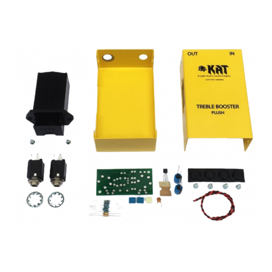
So, what's in the kit?
Well, everything you need to successfully build the TB except for a few hand tools and a battery.
Advertisement

Related Manuals for KAT TB PLUSH KIT


Summary of Contents for KAT TB PLUSH KIT
- Page 1 Firstly, a little info on the TB. For starters, the components provided are the best for the job in-hand. They are the same components used for the builds of many KAT TB’s and Fryer Sound TB Touring, Deluxe and Plus Treble Boosters. The circuit board has been specially designed for the kit so that the build can be easy with all components identified on the board.
- Page 2 Here are the only tools you will need to build this kit: 1. Soldering Iron (25 – 40W) 2. Multicore solder 3. Cutters 4. No. 1 Pozidriv screwdriver 5. Large pair of pliers We would suggest that you set up on a large piece of cardboard or cutting board along these lines.
- Page 3 The first thing we need to do is pre-form (bend) the legs ready to insert the device in the board. To do this, hold the resistor in your hand with your thumb nail resting on the end of the resistor body: With your finger, bend the leg towards you at 90 degrees so that the lead is formed around your thumb nail.
- Page 4 Your formed legs now looking like this and ready to be dropped into the board. Find the location of ‘R1’ on the board and drop the resistor into the holes from above. It is good practice (but not necessary) to orientate the resistors so that the colour codes either read from left to right, or from bottom to top.
- Page 5 You should now have a board populated with 8 resistors. There is a ‘check picture’ further along in these instructions if you want to check you have the correct components in the correct place before you solder. If you are colour-blind in any way, or have sight impairment, you can check values with a multi-meter touched across the ends of each resistor in turn.
- Page 6 Now it’s time to move on to the small polyester and ceramic capacitors. The value of which is either written on the front or the top of each device. Again, further help can be found at the back of this piece. As per the resistors, you can drop the four capacitors into their respective holes as detailed.
- Page 7 Board inverted ready for soldering. Small capacitors now soldered in, you can cut the excess leads off with your cutters. Your board should now look like this!.. Now for the larger Electrolytic capacitors. There are two in this circuit and both are the same value, so you don’t need to worry about fitting the wrong one.
- Page 8 The board also has polarising orientation marks within the idents. The square solder pad is the plus and the round, the minus. On these boards, the plus side also has a (+) symbol next to it. So, as per the pic to the right, the long leg goes in the square hole!..
- Page 9 Capacitors and resistors now installed. Your board should look like this!… Transistor-Time!... The transistor is the ‘engine-room’ of the Treble Booster. They are all different, have different responses and gains and can be right diva’s if not handled with care. Firstly, they HAVE to be oriented the correct way around FIRST TIME, otherwise they will self -destruct on power-up! Some can be a...
- Page 10 If you now look at the board, you’ll notice that we have put a curved ident on the board to one side of the holes. This curved ident signifies the round side of the transistor. Here is the board with the transistor dropped in.
- Page 11 This is how your board should now look! Check-Board Picture. Use this to make sure everything is installed and in the right place. Time to install the jack sockets. These are both 3 pole units so can be fitted in either position.
- Page 12 Before soldering-in the jacks, it’s worth making sure they align with the holes in the case. If they don’t, re-seat the jacks so they do. You can now invert the board (they won’t fall out believe me!) and solder the lugs in place.
- Page 13 Once un-twisted, use your cutters to strip off the insulation 5mm from the end of each wire. Keep a firm grip on the cable whilst stripping to ensure the two wires remain aligned. Twist the bare tinned copper strands into tightly smooth ends.
- Page 14 They are marked on the front with ‘9V’ (Red) and ‘0V’ (Black). Carefully solder the wires this time on the component side! Then trim off the excess wire. The final part of the electronics assembly is the battery box. This too is polarised and clearly marked at the terminal end.
- Page 15 The electronics assembly is now complete and ready to be installed into the case. The finished assembly can now be lowered through the battery hole in the case. If you locate the first jack through the hole first, the rest just follows. Board assembly now through, you can drop the battery box into place.
- Page 16 Note orientation of battery box. Use the two countersunk screws to secure the battery box. Do not over-tighten otherwise you will crack the box mounting flange. Your Battery box should now look like this.. Remove the jack nuts and plain washers and fit the two locking washers provided.
- Page 17 Align the OUTPUT jack with the hole in the case that has bare metal showing. This is to ensure the box is properly connected to the signal ground otherwise the unit will hum! Insert the board and secure with the plain washers and nuts.
- Page 18 Fit the first screw to approximately half its depth. Fit the other three screws, again, to half their depth. The alignment of these holes can sometimes be tight due to the powder coating. If the screws do not align with the threaded inserts, do not force it, but open up the case top holes with a 3.5mm drill bit before re-trying.
- Page 19 Your finished TB should now look very much like this beauty and sound incredible!
- Page 20 Helpful Bits. The TB PLUSH Schematic Resistors and small capacitors guide...
Need help?
Do you have a question about the TB PLUSH KIT and is the answer not in the manual?
Questions and answers