
Related Manuals for Ultraflex UP 20 F


Summary of Contents for Ultraflex UP 20 F
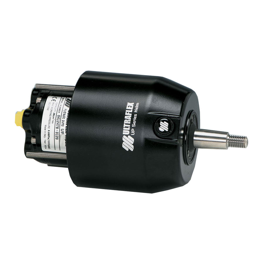
- Page 1 Installation and Maintenance Manual PUMP FOR HYDRAULIC STEERING SYSTEMS UP 20 F UP 20 T ULTRAFLEX page 1 pag. 25 page 49 SOCIO (Dr./Dis./Des. n° 32943 07/02/2017) (REV 0)
- Page 2 Products for pleasure boats are constantly tested to check their conformity with the 2013/53/EU. "ULTRAFLEX has over 80 years of experience in the marine industry and is a world leader in the production of mechanical, hydraulic and electronic steering systems, control boxes and steering wheels for any kind of pleasure, fishing or commercial boats.
-
Page 3: Table Of Contents
ULTRAFLEX Installation and maintenance manual TABLE OF CONTENTS DOCUMENT REVISIONS ..............................4 MANUAL USE AND SYMBOLS USED ..........................5 INFORMATIVE LETTER ..............................6 WARRANTY ..................................6 SECTION 1 - PRODUCT DESCRIPTION HYDRAULIC STEERING SYSTEM OPERATION ....................7 WARNINGS FOR THE CORRECT PRODUCT USE ....................7 SYSTEM CONFIGURATIONS .......................... -
Page 4: Document Revisions
ULTRAFLEX Installation and maintenance manual DOCUMENT REVISIONS Rev. Date Revision description 07/02/2017 First edition page 4 of 71 - PUMP FOR HYDRAULIC SYSTEMS... -
Page 5: Manual Use And Symbols Used
ULTRAFLEX Installation and maintenance manual MANUAL USE AND SYMBOLS USED THE INSTALLATION AND MAINTENANCE MANUAL is the document accompanying the product from its sale to its replacement and discharge. The manual is an important part of the product itself. It is necessary to read carefully the manual, before ANY ACTIVITY involving the product, handling and unloading included. -
Page 6: Informative Letter
We remind you that only marked steering systems must be used on the boats marked We inform you that the ULTRAFLEX warranty is null if some ULTRAFLEX components are installed on a steering system together with products of other brands. -
Page 7: Section 1 - Product Description
A well balanced steering system needs a correct choice of the pump for the cylinder. ULTRAFLEX produces different pump models, which have different capacity (cm of oil moved each steering wheel turn) and for each type of installation. -
Page 8: System Configurations
ULTRAFLEX Installation and maintenance manual 1.3 System configurations The pump UP20 can be installed in a single or double steering system and used with different types of configurations of front, side or inboard cylinders. WARNING The pumps model UP20 can be installed in a single or double steering system and used with cylinders UC68, UC69, UC94. -
Page 9: Pump Technical Features
Max. steering wheel dish 114 mm (4,5 in.) 152 mm (6 in.) Weight 3,6 kg (8 lbs) 3,9 kg (8,5 lbs) OL150 Ultraflex OL150 Ultraflex UP20 F 57,2 mm 103,5 mm 82 mm [2,3 in.] [4,1 in.]... -
Page 10: Section 2 - Transport
ULTRAFLEX Installation and maintenance manual 2 TRANSPORT 2.1 General warnings The pump UP20 F weight with its packaging is 4,5kg (9,92 pounds); the pump UP20 T weight with its packaging is 4,8 kg (10,58 pounds) and so they can be handled manually. -
Page 11: Section 3 - Installation
ULTRAFLEX Installation and maintenance manual 3 INSTALLATION 3.1 Tools necessary for the installation of pump UP20F Torque MOLYKOTE® 1000 Screwdriver Drill Open end Open end Open end wrench wrench wrench wrench 19 mm 10 mm 11/16" 3.2Pump UP20 F installation min. - Page 12 ULTRAFLEX Installation and maintenance manual By using the proper template supplied with this manual, make the 3 holes (4) for the 3 dowels and the central hole (5). 5 Position the pump (2) on the dashboard front side (6) interposing the gasket (7) and fix it by...
-
Page 13: Tools Necessary For The Installation Of Pump Up20T
ULTRAFLEX Installation and maintenance manual 3.3 Tools necessary for the installation of pump UP20T * The tools to assemble tilt X52 are listed in the manual enclosed to tilt X52. Open end Screwdriver wrench 13 mm 3.4 Pump UP20 T installation NOTICE min. - Page 14 ULTRAFLEX Installation and maintenance manual Screw the nuts completely on the corresponding 90° unions (3), Fit and screw the Connection for additional station unions manually as indicated in the picture until they are inserted completely. Turn them until they are positioned correctly with respect to...
- Page 15 68 lbs in) and fix the tilt with screws (9) (torque of 5 Nm - 44 lbs in). NOTICE The kit F ULTRAFLEX supplied separately (see the corresponding instructions) can be used on pump UP20 T to simplify the hydraulic system filling and purging. page 15...
-
Page 16: Types Of Installation
3.6 Hose connection to the system Connect the hydraulic hoses ULTRAFLEX kit OB (supplied separately) joining the pump and the cylinder by following the instructions given in the installation manual of the kit OB. - Page 17 ULTRAFLEX Installation and maintenance manual MAIN STEERING STATION ADDITIONAL STEERING STATION Connect pipes as shown in picture following the manual instructions. MAIN STEERING STATION ADDITIONAL STEERING STATION Kit OB-2S Kit OB Kit OB-2S Kit OB Kit OB cylinder cylinder connecting...
-
Page 18: Filling And Purging
- Q8 HAYDN15 NOTICE ULTRAFLEX will not be able to ensure the compatibility of the above mentioned oils with OL150 if the oil manufacturers vary their formulation; in particular, it will not be able to ensure its compliance with standard ISO 10592 concerning hydraulic steering systems. -
Page 19: Positioning Of The Oil Bottle
ULTRAFLEX Installation and maintenance manual 3.7.1 Positioning of the oil bottle To carry out this operation, it is necessary to use the oil filling kit (1 needle, 1 transparent pipe, 1 pipe connection and 1 spout for the oil bottle). This kit is NOT supplied. -
Page 20: Section 4 - Safety Warnings
4.1 Safety warnings during use and installation RESPECT STRICTLY the following safety rules. ULTRAFLEX declines all responsibility in case the user does not follow these rules and it is not responsible for negligence during the use of the system. DANGER DO NOT PUT HANDS BETWEEN THE MOVING PARTS. -
Page 21: Section 5 - Maintenance
To keep a suitable oil level in the tank, fill and bleed the system as described in this manual in paragraph 3.9 and in the bleeding procedure of ULTRAFLEX cylinders. Check the hose and the entire system wear, the nut and bolt tightening every six months and make sure that they are not damaged. Clean the system using water and non-abrasive soap. - Page 22 • Drain the filling and bleeding system. when the boat is not • Wrong oil has been used. moving. WARNING ULTRAFLEX is not responsible for damage caused fluids that recommended in this manual and so the warranty is cancelled.
-
Page 23: Section 6 - Dismantling
ULTRAFLEX Installation and maintenance manual 6 DISMANTLING 6.1 Dismantling When for any reason, the steering system is put out of service, it is necessary to follow some rules in order to respect the environment. Sheaths, pipelines, plastic or non-metallic components must be disassembled and disposed of separately. - Page 24 ULTRAFLEX Installation and maintenance manual NOTES page 24 of 71 - PUMP FOR HYDRAULIC SYSTEMS...
- Page 25 Manuale di installazione e manutenzione POMPA PER SISTEMI DI GUIDA IDRAULICI UP 20 F UP 20 T ULTRAFLEX SOCIO...
- Page 26 Gentile Cliente, La ringraziamo per aver scelto un prodotto ULTRAFLEX. ULTRAFLEX è da anni un punto di riferimento nei sistemi di guida nel settore della nautica da diporto e professionale. Da sempre la produzione ULTRAFLEX è sinonimo di grande affidabilità e sicurezza.
- Page 27 ULTRAFLEX Manuale di installazione e manutenzione INDICE GENERALE INDICE DELLE REVISIONI DEL DOCUMENTO ......................28 USO DEL MANUALE E SIMBOLOGIA IMPIEGATA ....................... 29 LETTERA INFORMATIVA ..............................30 GARANZIA ..................................30 SEZIONE 1 - DESCRIZIONE DEL PRODOTTO FUNZIONAMENTO DI UN SISTEMA DI GUIDA IDRAULICO ................31 AVVERTENZE PER IL CORRETTO UTILIZZO DEL PRODOTTO ................
- Page 28 ULTRAFLEX Manuale di installazione e manutenzione INDICE DELLE REVISIONI DEL DOCUMENTO Rev. Data Descrizione della revisione 07/02/2017 Prima realizzazione pag. 28 di 71 - POMPA PER SISTEMI IDRAULICI...
- Page 29 ULTRAFLEX Manuale di installazione e manutenzione USO DEL MANUALE E SIMBOLOGIA IMPIEGATA Il MANUALE DI INSTALLAZIONE E MANUTENZIONE è il documento che accompagna il prodotto dal momento della sua vendita fino alla sua sostituzione e smaltimento. Risulta cioè essere parte integrante dello stesso.
- Page 30 GARANZIA ULTRAFLEX garantisce che i suoi prodotti sono costruiti a regola d'arte e che sono privi di difetti di fabbricazione e di materiali. Questa garanzia è valida per un periodo di due anni decorrenti dalla data di fabbricazione dei prodotti ad eccezione dei casi in cui questi siano installati ed usati su barche da lavoro o comunque su barche ad utilizzo commerciale, nel qual caso la garanzia è...
- Page 31 I sistemi idraulici di guida ULTRAFLEX sono progettati in conformità alla normativa UNI-EN-ISO 10592 ed alla A.B.Y.C. P21. I sistemi di guida ULTRAFLEX sono in grado di operare in un campo di temperatura ambiente compreso tra -18°C (0°F) e +77°C (+170°F), tutti i loro componenti sono stati realizzati specificatamente per l'ambien- te marino, utilizzando materiali e processi di fabbricazione che offrono grande durata e sicurezza anche nelle condizioni più...
- Page 32 ULTRAFLEX Manuale di installazione e manutenzione 1.3 Configurazioni del sistema La pompa modello UP20 può essere installata in un sistema di guida singolo o doppio e utilizzata in accop- piamento a diversi tipi di cilindro a montaggio frontale, laterale o entrobordo.
- Page 33 [3,22 in.] 76mm [3 in.] UP20 T 174 mm [6,8 in.] 247 mm [9,7 in.] 6° ATTENZIONE La pompa UP20 T può essere utilizzata solo con il tilt ULTRAFLEX X52 (fornito a parte). pag. 33 di 71 POMPA PER SISTEMI IDRAULICI...
- Page 34 ULTRAFLEX Manuale di installazione e manutenzione 2 TRASPORTO 2.1 Avvertenze generali Il peso della pompa UP20 F con il suo imballo è 4,5 Kg (9,92 pounds), quello della pompa UP20 T è 4,8 Kg (10,58 pounds). La loro movimentazione può quindi essere effettuata manualmente.
- Page 35 ULTRAFLEX Manuale di installazione e manutenzione 3 INSTALLAZIONE 3.1 Utensili necessari per l'installazione della pompa UP20F Chiave MOLYKOTE® 1000 Cacciavite Trapano Chiave Chiave Chiave dinamometrica esagonale esagonale esagonale 19 mm 10 mm 11/16" 3.2 Installazione della pompa UP20 F min. 82 mm [3,22 in.] Scegliere una posizione adatta per l'installazione spessore max.
- Page 36 ULTRAFLEX Manuale di installazione e manutenzione Utilizzando l'apposita dima allegata al pre- sente manuale eseguire sul cruscotto i 3 fori per i 3 grani (4) e il foro centrale (5). Posizionare la pompa (2) dalla parte frontale del cruscotto (6) infrapponendo la guarnizione...
- Page 37 ULTRAFLEX Manuale di installazione e manutenzione 3.3 Utensili necessari per l'installazione della pompa UP20T * Gli utensili per montare il tilt X52 sono indicati sul manuale allegato al tilt X52. Chiave Cacciavite esagonale 11/16" 3.4 Installazione della pompa UP20 T NOTA min.
- Page 38 ULTRAFLEX Manuale di installazione e manutenzione Avvitare completamente i dadi sui relativi raccordi a 90° (3), imboccare ed avvitare i raccordi a mano come indicato in figura fino al loro completo inserimento, orientarli fino a posizionarli nel modo Collegamento per connessione più...
- Page 39 (9) (coppia 5 Nm - 44 lbs in). NOTA Sulla pompa UP20 T per facilitare le operazioni di riempimento e spurgo del sistema idraulico, è possibile utilizzare il Kit F ULTRAFLEX fornito separatamente (vedere relative istruzioni). pag. 39 di 71 POMPA PER SISTEMI IDRAULICI...
- Page 40 3.6 Collegamento dei tubi all'impianto Connettere i tubi idraulici ULTRAFLEX kit OB (forniti a parte) di collegamento tra la pompa e il cilindro seguendo le istruzioni riportate sul manuale di installazione del kit OB.
- Page 41 ULTRAFLEX Manuale di installazione e manutenzione STAZIONE DI GUIDA PRIMARIA STAZIONE DI GUIDA SUPPLEMENTARE Collegare i tubi come indicato in figura seguendo le istruzioni dei relativi manuali. STAZIONE DI GUIDA SUPPLEMENTARE STAZIONE DI GUIDA PRIMARIA Kit OB-2S tubo di collega-...
- Page 42 - Q8 HAYDN15 NOTA ULTRAFLEX non potrà garantire la compatibilità degli oli citati con OL150 in caso di variazione alle formulazioni da parte dei produttori degli oli stessi, in particolare non potrà garantirne la rispondenza alla ISO 10592 relativa ai sistemi di guida idraulici. Eventuali cali prestazionali e/o di durata non saranno in nessun caso imputabili ad ULTRAFLEX.
- Page 43 ULTRAFLEX Manuale di installazione e manutenzione 3.7.1 Posizionamento della bottiglia dell'olio Per effettuare questa operazione è necessario il kit di riempimento olio (1 spillo spillo, 1 tubo trasparente, 1 raccordo portatubo e 1 beccuccio per bottiglia olio) NON fornito in dotazione.
- Page 44 RISPETTATE TASSATIVAMENTE le precauzioni ed i criteri di sicurezza indicati qui di seguito. ULTRAFLEX. declina ogni responsabilità nel caso in cui l'utilizzatore non li osservi, così come non è respon- sabile per qualsiasi tipo di negligenza che venga commessa durante l'utilizzo del sistema.
- Page 45 Per mantenere un idoneo livello dell'olio nel serbatoio procedere al riempimento ed allo spurgo del sistema come indicato nel manuale al paragrafo 3.7 e nelle procedure di spurgo dei cilindri ULTRAFLEX. Controllare l'usura dei tubi e dell'intero sistema, il fissaggio dei dadi e dei bulloni ogni sei mesi ed assicurarsi della loro perfetta integrità.
- Page 46 è ferma. AVVERTENZA Eventuali danni causati dall'uso di fluidi diversi da quelli raccomandati in questo manuale, non sono in alcun modo imputabili a ULTRAFLEX e annullano auto- maticamente la garanzia. La timoneria è rigida e diffi- cilmente manovrabile, anche AVVERTENZA •...
- Page 47 ULTRAFLEX Manuale di installazione e manutenzione 6 SMANTELLAMENTO 6.1 Smantellamento Qualora si intenda, per qualsiasi motivo, mettere fuori servizio il sistema di guida, è necessario osser- vare alcune regole fondamentali atte a salvaguardare l’ambiente. Guaine, condotti flessibili, componenti di materiale plastico o comunque non metallico, dovranno essere smon- tati e smaltiti separatamente.
- Page 48 ULTRAFLEX Manuale di installazione e manutenzione NOTE pag. 48 di 71 - POMPA PER SISTEMI IDRAULICI...
- Page 49 Manuel d'installation et d'entretien POMPE POUR SYSTEMES DE GOUVERNEMENT HYDRAULIQUES UP 20 F UP 20 T ULTRAFLEX SOCIO...
- Page 50 Tous les produits ULT RAFLEX sont conçus et fabriqués pour assurer toujours les performances les meilleures. Pour assurer votre sécurité et pour maintenir toujours un niveau de qualité élevé ULTRAFLEX ne garantit ses produits que si les pièces de rechange originales sont utilisées (voir annexe "Application Spare Parts").
- Page 51 ULTRAFLEX Manuel d'installation et d'entretien INDEX GENERAL INDEX DES REVISIONS DU DOCUMENT ........................52 EMPLOI DU MANUEL ET SYMBOLES UTILISES ......................53 LETTRE D'INFORMATION .............................. 54 GARANTIE ..................................54 SECTION 1 - DESCRIPTION DU PRODUIT FONCTIONNEMENT D'UN SYSTEME DE GOUVERNEMENT HYDRAULIQUE ..........55 AVERTISSEMENTS POUR L'EMPLOI CORRECT DU PRODUIT ...............
-
Page 52: Index Des Revisions Du Document
ULTRAFLEX Manuel d'installation et d'entretien Rév. Date Description de la révision 07/02/2017 Première réalisation page 52 de 71 - POMPE POUR SYSTEMES HYDRAULIQUES... -
Page 53: Emploi Du Manuel Et Symboles Utilises
ULTRAFLEX Manuel d'installation et d'entretien EMPLOI DU MANUEL ET SYMBOLES UTILISES Le MANUEL D'INSTALLATION ET D'ENTRETIEN est le document qui accompagne le produit de sa vente jusqu'à son remplacement et sa démolition. C'est donc une partie fondamentale du manuel lui-même. -
Page 54: Lettre D'information
GARANTIE La Société ULTRAFLEX garantit que ses produits sont fabriqués à règles d'art et qu'ils n'ont aucun défaut de fabrication et de matériels. Cette garantie a une validité de deux années à partir de la date de fabrication des produits à l'exception des cas où... -
Page 55: Section 1 - Description Du Produit
Un système de gouvernement équilibré et facile à manoeuvrer demande un choix correct du type de pompe à accoupler au vérin. ULTRAFLEX produit plusieurs modèles de pompes, dont les différences sont le débit (cm d'huile déplacés à... -
Page 56: Configurations Du Systeme
ULTRAFLEX Manuel d'installation et d'entretien 1.3 Configurations du système La pompe modèle UP20 peut être installée dans un système de gouvernement unique ou double et utilisées avec différents types de configurations de vérins à assemblage frontal, latéral ou in-bord. AVERTISSEMENT Les pompes modèle UP20 peuvent être installées dans un système de gouvernement unique ou double et... -
Page 57: Caracteristiques Techniques Des Pompes
[3,22 in.] 76mm [3 in.] UP20 T 174 mm [6,8 in.] 247 mm [9,7 in.] 6° ATTENTION La pompe UP20 T peut être utilisée seulement avec le tilt ULTRAFLEX X52 (fourni séparément). page 57 de 71 POMPE POUR SYSTEMES HYDRAULIQUES... -
Page 58: Section 2 - Transport
ULTRAFLEX Manuel d'installation et d'entretien 2 TRANSPORT 2.1 Avertissements généraux Le poids de la pompe UP20 F avec son emballage est 4,5 Kg (9,92 pounds), celui de la pompe UP20 T est 4,8 Kg (10,58 pounds). Elles peuvent donc être déplacées manuellement. -
Page 59: Section 3 - Installation
ULTRAFLEX Manuel d'installation et d'entretien 3 INSTALLATION 3.1 Outils nécessaires pour l'installation de la pompe UP20F Clé MOLYKOTE® 1000 Tournevis Perceuse Clé Clé Clé dynamométrique hexagonale hexagonale hexagonale 19 mm 10 mm 11/16" 3.2 Installation de la pompe UP20 F min. - Page 60 ULTRAFLEX Manuel d'installation et d'entretien 4 A l'aide du gabarit adéquat joint à ce manuel percer sur le tableau de bord les 3 trous pour les 3 goujons (4) et le trou central (5). Positionner la pompe (2) de la partie fronta- le du tableau de bord (6) en interposant la garniture (7) et la fixer en insérant les 3...
-
Page 61: Outils Necessaires Pour L'installation Des Pompe Up20 T
ULTRAFLEX Manuel d'installation et d'entretien 3.3 Outils nécessaires pour l'installation de la pompe UP20T * Les outils nécessaires pour l'assemblage du tilt X52 sont indiqués dans le manuel joint au tilt X52. Chiave Cacciavite esagonale 11/16" 3.4 Installation de la pompe UP20 T NOTE min. - Page 62 ULTRAFLEX Manuel d'installation et d'entretien Visser complètement les écrous sur les raccords relatifs à 90° (3). Placer et visser les raccords manuellement comme indiqué dans Connexion de raccordement poste la figure jusqu'à les insérer totalement, les supplémentaire orienter jusqu'à les positionner dans la façon la plus adéquate à...
- Page 63 44 lbs in). NOTE Sur la pompe UP20 T pour faciliter les opérations de remplissage et de purge du système hydraulique on peut utiliser le Kit F ULTRAFLEX fourni séparément (voir les instructions correspondantes). page 63 de 71 POMPE POUR SYSTEMES HYDRAULIQUES...
-
Page 64: Types D'installation
évent. 3.6 Connexion des tuyaux au système Connecter les tuyaux hydrauliques ULTRAFLEX kit OB (fournis séparément) de connexion entre la pompe et le vérin selon les instructions données dans le manuel d'installation du kit OB. - Page 65 ULTRAFLEX Manuel d'installation et d'entretien POSTE DE GOUVERNEMENT PRIMAIRE POSTE DE GOUVERNEMENT SUPPLEMENTAIRE Connecter les tuyaux comme indiqué dans la figure selon les instructions des manuels relatifs. POSTE DE GOUVERNEMENT SUPPLEMENTAIRE POSTE DE GOUVERNEMENT PRIMAIRE Kit OB-2S tuyau de Kit OB-2S...
-
Page 66: Remplissage Et Purge
L'huile hydraulique OL150 est spécifiquement formulée pour ULTRAFLEX afin de maintenir le plus longtemps possible pendant le temps le haut niveau de qualité et de performance des produits ULTRAFLEX. Sa formule particulière "Sans Zinc" favorise la protection contre l’oxydation marine. Le mélange particulier des composants antiusures et stabilisants, dont OL150 est composé, permettent d’obtenir un résultat optimal... -
Page 67: Positionnement De La Bouteille De L'huile
ULTRAFLEX Manuel d'installation et d'entretien 3.7.1 Positionnement de la bouteille de l'huile Pour effectuer cette opération il faut avoir le kit de remplissage huile (1 aiguille pointeau, 1 tuyau transparent, 1 raccord porte tuyau et 1 bec pour la bouteille huile) NON fourni. -
Page 68: Section 4 - Avertissements De Securite
RESPECTER RIGOUREUSEMENT les précautions et les critères de sécurité indiqués ci-dessous. La Société ULTRAFLEX. décline toute responsabilité au cas où l'usager ne les respecterait pas; elle n'est pas non plus responsable pour tout type de négligence commise pendant l'emploi du système. -
Page 69: Section 5 - Entretien
3.7 et dans les procédures de purge des vérins ULTRAFLEX. Tous les six mois contrôler l'usure des tuyaux et de tout le système, la fixation des écrous et des boulons et s'assurer qu'ils soient parfaitement intacts. Nettoyer le système avec de l'eau et du savon pas abrasif. - Page 70 à manoeuvrer, même de remplissage et de purge. quand le bateau est à • Emploi incorrect de l'huile. l'arrêt. AVERTISSEMENT ULTRAFLEX décline Société toute responsabilité garantie automatiquement annulée en cas de dommages causés par l'emploi de fluides différents de ceux qui sont recommandés dans ce manuel.
-
Page 71: Section 6 - Demolition
ULTRAFLEX Manuel d'installation et d'entretien 6 DEMOLITION 6.1 Démolition Si le système de gouvernement doit être mis hors service pour quelques raisons que ce soit, les règles fondamentales suivantes doivent être observées pour la protection de l'environnement. aines, conduits flexibles, composants de matériel plastique ou non métalliques, devront être désassemblés et éliminés séparément. - Page 72 ULTRAFLEX S.p.A. 16015 Casella (Genova) Italia - Via Crose, 2...
- Page 73 DIMA DI FORATURA PER APPLICAZIONE AD INCASSO. FLUSH MOUNTING DRILLING TEMPLATE. ATTENZIONE! WARNING! Scala 1:1 Non fotocopiare la presente Don't copy the drilling dima di foratura. template. [Scale 1:1] Le dimensioni reali potrebbero The real dimension could risultare alterate. result altered. 101 mm [3.98"] 4 HOLES Ø6.5 mm [Ø...
- Page 74 NOTA: lo spessore massimo del cruscotto per l'installazione del presente kit è di 42.5 mm. NOTE: to install this kit, maximum dashboard width allowed is 1.65". Applicare la guarnizione fornita con la pompa (3) e fissare la piastra in acciaio (1) alla base della pompa (2) tramite le apposite viti, le rondelle ed i dadi autobloccanti (forniti con la pompa) come indicato in Fig.
Need help?
Do you have a question about the UP 20 F and is the answer not in the manual?
Questions and answers