Table of Contents
Advertisement
Advertisement
Table of Contents

Subscribe to Our Youtube Channel
Related Manuals for Digital-Ally Laser Ally Speed LIDAR


Summary of Contents for Digital-Ally Laser Ally Speed LIDAR
- Page 1 Laser Ally Speed LIDAR Operator Guide Doc: 30157 Rev. 12...
-
Page 2: Table Of Contents
Laser Ally Speed LIDAR Operator Guide Table of Contents Introduction ..................5 Notices and Precautions ..............6 Caution: Class 1 Laser Product ............6 Caution: Precision Instrument ............6 Caution: Use Care When Cleaning Optics ........6 Caution: Do not Point the Device at the Sun ........7 Unpacking and Checking the LIDAR Device ......... - Page 3 Laser Ally Speed LIDAR Operator Guide Jam / ECM Attempt Indication ........... 14 Basic Operation .................. 15 Battery Installation ................ 16 Powering On .................. 16 Selecting Speed Mode ..............17 Using the HUD Sighting System ............. 17 Roadside Setup ................18 Measuring Vehicle Speeds .............
- Page 4 Laser Ally Speed LIDAR Operator Guide Daily Recommended Test ..............29 Fixed Distance Test ................30 Alignment Test ................31 Certification ..................31 Maintenance and General Care ............32 Cleaning ..................32 Storage ...................32 General Handling ................33 LIMITED WARRANTY ................34 Troubleshooting and Service .............36 Specifications ..................37 Appendix A –...
-
Page 5: Introduction
Laser Ally Speed LIDAR Operator Guide Introduction Thank you for purchasing the Digital Ally LIDAR The Laser Ally Speed LIDAR is a high performance electro-optical product providing accurate speed and distance measurements custom designed for the law enforcement community. The LIDAR... -
Page 6: Notices And Precautions
Notices and Precautions Caution: Class 1 Laser Product The Laser Ally Speed LIDAR is a Class 1 Laser product in accordance with U.S. 21CFR parts 1040.10 and 1040.11, which is safe for use in all intended operation modes. However, standard precautions should always be taken with laser products: ... -
Page 7: Caution: Do Not Point The Device At The Sun
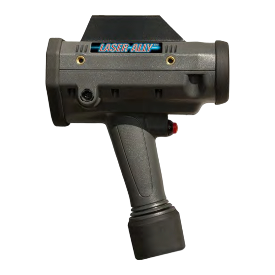
Laser Ally Speed LIDAR Operator Guide Caution: Do not Point the Device at the Sun Do not aim your LIDAR directly at the sun as this could damage internal components. Unpacking and Checking the LIDAR Device The basic Laser Ally LIDAR unit includes the following items: 1. - Page 8 Laser Ally Speed LIDAR Operator Guide Receiver Aperture Transmitter Aperture Laser Trigger Battery Compartment Head Up Display (HUD) Rear Panel Display Control Keypad Data Connector Accessory Attachment Points (i.e. Tri-Pod) Digital Ally, Inc.|Doc. 30157 Rev 12...
-
Page 9: Display Descriptions
Laser Ally Speed LIDAR Operator Guide Display Descriptions The following figures show typical displays for both the rear panel and (Head-Up Display) HUD. Special menu displays and HUD indicators will be covered in their respective sections of this manual. Rear Panel Display (LIDAR in Speed Mode) -
Page 10: Controls And Indicators
Laser Ally Speed LIDAR Operator Guide Controls and Indicators The Laser Ally LIDAR has an ergonomically styled handle with a sealed laser fire trigger and an easy to use back panel keypad to select modes of operation and tailor settings for particular conditions. -
Page 11: Rear Panel Controls
Laser Ally Speed LIDAR Operator Guide Rear Panel Controls All remaining controls are located on the rear panel, adjacent to the display. The following diagram shows the location of the various buttons. Further descriptions of the button functions are detailed in the following sections. -
Page 12: Daily Test Initiation
Laser Ally Speed LIDAR Operator Guide Daily Test Initiation Press to initiate the system Daily Test sequence. The operator will be prompted to complete each test required. During the test all critical internal timing and electronic components will be checked, all display components will be illuminated to allow the operator to verify each segment. -
Page 13: Menu/Exit Menu
Laser Ally Speed LIDAR Operator Guide Obstruction Mode: Only ellipse indicator is on; minimum range is adjusted to ignore obstruction by requiring the obstruction to be targeted with an initial range reading, and then verified with enter button; (see “Advanced Controls and Modes”). -
Page 14: Jam / Ecm Attempt Indication
Laser Ally Speed LIDAR Operator Guide HUD. (Note: The rear panel low battery symbol will be partially filled in). The unit may continue to be used, and may last a considerable amount of time particularly with low volume settings; however a replacement set of batteries should be handy to avoid down time. -
Page 15: Basic Operation
Laser Ally Speed LIDAR Operator Guide target vehicle, such as high beam headlights or sun reflections can cause the jam indicators to turn on. If you experience any difficulty in obtaining a speed-calculation when “Jam” is indicated, try moving the HUD aiming point to another location on the vehicle. -
Page 16: Battery Installation
Laser Ally Speed LIDAR Operator Guide Battery Installation Unscrew the end cap at the bottom of the handle by turning counter-clockwise. Insert two “C” cell batteries, positive end first, into the handle compartment. Replace the end cap and screw clockwise until the cap is securely in place. -
Page 17: Selecting Speed Mode
Laser Ally Speed LIDAR Operator Guide Selecting Speed Mode The LIDAR will normally power up in “Speed” mode, unless it was recently used in a different mode. If “Speed” mode is not displayed on power up, simply press until the back panel displays:... -
Page 18: Roadside Setup
Laser Ally Speed LIDAR Operator Guide Roadside Setup When first learning to use the Laser Ally LIDAR, it is best to select a straight stretch of roadway with a line of sight of 150 metres or more. Approaching or receding vehicles should be targeted such that your line of sight through the HUD is as parallel as possible to the path of the target vehicle. -
Page 19: Speed Display Lock
Laser Ally Speed LIDAR Operator Guide Note: The above acquisition sequence can happen very quickly and you may simply hear the high frequency tone and see the speed display immediately. A positive speed-calculation will be shown for an approaching vehicle (this will be a whole number, less the “+” symbol) while receding vehicles are indicated with a negative reading. -
Page 20: Range Mode
Laser Ally Speed LIDAR Operator Guide turning off the HUD and displaying “Power-Save” on the rear panel along with the locked reading. In the Power-Save state, a first laser trigger pull will “wake” the LIDAR but retain the locked reading. A second pull will then clear the reading. -
Page 21: Advanced Controls And Modes
Laser Ally Speed LIDAR Operator Guide Advanced Controls and Modes Weather and Obstruction Modes button is used to select one of three environmental operating modes: 1. Normal Mode 2. Weather Mode 3. Obstruction Mode To select a particular Weather/Obstruction mode simply press the button. -
Page 22: Obstruction Mode
Laser Ally Speed LIDAR Operator Guide to select Weather Mode; wait for a couple of seconds and the LIDAR will return to Range or Speed mode with the Weather mode activated. The Weather indicator will be displayed in both the HUD and the rear panel display. -
Page 23: Minimum And Maximum Ranges (Range Window)
Laser Ally Speed LIDAR Operator Guide Minimum and Maximum Ranges (Range Window) While in Speed mode, the Minimum and Maximum Range settings are used to set limits (or a range window) outside of which, speed- calculation will not be displayed. -
Page 24: Direction Filter
Laser Ally Speed LIDAR Operator Guide acquired outside of this range window, a target acquired audible tone will be heard but dashes ( - - - - ) will be displayed in the HUD and on the rear display in the speed reading area. In addition, the word “window”... -
Page 25: Differential Distance Test
Laser Ally Speed LIDAR Operator Guide The rear panel will also display the indication “Approach” or “Recede” to indicate that a vehicle has been targeted traveling in a direction opposite to that of the Filter. Differential Distance Test Note: The Differential Distance Test is an optional accuracy check preferred by some jurisdictions. -
Page 26: Timed Distance Mode
Laser Ally Speed LIDAR Operator Guide If the LIDAR does not pass the test, carefully recheck the distances, reposition the targets and LIDAR, if necessary, and then repeat the test. If the unit continues to fail the test, please contact customer service. - Page 27 Laser Ally Speed LIDAR Operator Guide Note: If the operator elects to shoot the distance to the reference objects, please ensure both reference points are on one side of the operator and in a straight line with the operator’s position. The LIDAR will subtract the two readings to determine the distance.
-
Page 28: Load Defaults
Laser Ally Speed LIDAR Operator Guide To measure the average speed of additional vehicles, simply click the trigger once to clear the old reading and timer is re-armed for a new reading. Load Defaults The factory default settings for the LIDAR can be restored at any time by pressing then selecting “Load Defaults”... -
Page 29: Input / Output Port
Laser Ally Speed LIDAR Operator Guide Input / Output Port An eight-pin DIN style connector is located on the right side of the unit. This connector can be used to collect speed and range measurement data during operation using a special USB cable provided by Digital Ally. -
Page 30: Fixed Distance Test
Laser Ally Speed LIDAR Operator Guide Fixed Distance Test The Laser Ally LIDAR uses time of flight laser distance measurement as its core technology in calculating vehicle speed. Therefore, a quick check of unit’s ranging accuracy is suitable for daily confidence checks. -
Page 31: Alignment Test
Laser Ally Speed LIDAR Operator Guide Alignment Test The operator will be prompted to complete a horizontal and vertical alignment test of the HUD aiming reticle by selecting a target with straight boundaries such as a telephone pole or road sign at a distance of 30 metres or greater. -
Page 32: Maintenance And General Care
Laser Ally Speed LIDAR Operator Guide Maintenance and General Care Your Laser Ally LIDAR is designed to keep performing with very little user maintenance. Besides replacing the batteries, there are no user serviceable parts and the unit should NOT be disassembled. -
Page 33: General Handling
Laser Ally Speed LIDAR Operator Guide vibration into the LIDAR unit resulting in damage to internal components. General Handling The Laser Ally LIDAR is built to be rugged and endure many types of accident impacts and drops. However, please remember that much like a camera, the LIDAR is a precision optical instrument that should be handled with reasonable care. -
Page 34: Limited Warranty
Laser Ally Speed LIDAR Operator Guide LIMITED WARRANTY We warrant that our Laser Ally LIDAR System will be free from defects in workmanship and material for a period of 12 months (or any other negotiated term) from the date of purchase by the original purchaser. - Page 35 Laser Ally Speed LIDAR Operator Guide Damage to external parts of the unit such as buttons, connectors, wires, and cables, etc. Damage from use of the unit in hostile operating environments. We reserve the right to charge for repairs to a unit during the warranty period made necessary because of any of the foregoing causes at our standard rates for repair of units not under warranty.
-
Page 36: Troubleshooting And Service
Laser Ally Speed LIDAR Operator Guide Troubleshooting and Service Symptom Possible Causes Unit will not power up when 1. Replace batteries. trigger is pulled 2. Check that batteries are inserted correctly. Head Up Display is not visible Check HUD brightness setting Audio tone indicates an 1. -
Page 37: Specifications
Laser Ally Speed LIDAR Operator Guide Specifications Weight: 1.14 kg with batteries Dimensions: 11.4 x 17.1 x 24.8 cm Acquisition Time: 1/3 Second Speed Accuracy: +/- 1 Unit of Measure (One Sigma Standard Error) Minimum Range: Speed Mode 15 m... - Page 38 Laser Ally Speed LIDAR Operator Guide Environmental: Waterproof to IP67 Additional Features: Timed Distance (Stopwatch) Mode Obstruction Mode Advanced Anti-Jamming ECCM Digital Ally, Inc.|Doc. 30157 Rev 12...
-
Page 39: Appendix A - Cosine Effect
Laser Ally Speed LIDAR Operator Guide Appendix A – Cosine Effect The term “Cosine Effect” as typically used in law enforcement speed measurement, refers to the reduction of a vehicle’s measured speed using Radar or Laser systems as compared to the actual vehicle speed when targeting the vehicle at an angle.
Need help?
Do you have a question about the Laser Ally Speed LIDAR and is the answer not in the manual?
Questions and answers