
Related Manuals for Dini Argeo EGT scale series

Summary of Contents for Dini Argeo EGT scale series
- Page 1 EGT-BATCH1 USER GUIDE SOFTWARE FOR SINGLE PRODUCT DOSAGE SYSTEMS, IN LOADING OR UNLOADING Revision 1.00 Last update 01/02/2013...
- Page 2 Page intentionally left blank.
-
Page 3: Table Of Contents
EGT-BATCH1 USER GUIDE Table of contents INTRODUCTION ............................7 TECHNICAL SPECIFICATIONS ........................9 INSTALLATION ............................11 Case and dimensions ........................11 Power supply ........................... 12 Start up ............................13 Turning off the instrument ......................13 INDICATOR PARTS ............................ 15 Display ............................. 16 4.1.1 Display Indicators ........................ - Page 4 EGT-BATCH1 USER GUIDE Printouts ............................37 Setpoints ............................38 DOSAGE ..............................39 Automatic dosage of a product in loading ..................39 6.1.1 Dosage start ..........................39 6.1.2 Enabling loading phase ......................39 6.1.3 End of loading activity ......................40 6.1.4 Complete unloading ........................
- Page 5 EGT-BATCH1 USER GUIDE 6.10 Error messages ..........................54 6.11 Progressives ............................. 56 6.11.1 Additional value ........................56 6.11.2 Progressive digits ........................56 6.11.3 Ticket progressive ........................56 6.11.4 Lot progressive ........................56...
-
Page 7: Introduction
INTRODUCTION This manual was created to help you install and learn all about the functional possibilities of the purchased indicator. The instrument is suitable for use in various weighing environments. Not only does it have all the normal features of high-precision scales, but it also gives you the possibility to work in specific environments due to the functioning modes contained in the software implemented in the FLASH MEMORY on the internal board. - Page 8 INTRODUCTION Do not install in any area where there is a risk of explosion. The crossed-out wheeled bin on the product means that at the product end of life, it must be taken to separate collection or to the reseller when a new equivalent type of equipment is purchased.
-
Page 9: Technical Specifications
TECHNICAL SPECIFICATIONS 12 Vdc ( 8 ÷ 24 Vdc in the IO versions), with internal 100 ÷ 240 Vac (50÷60 POWER SUPPLY Hz) / 12 Vdc adapter. MAXIMUM POWER 16 VA. OPERATING TEMPERATURE From -10 to +40 °C. CONVERTER 24 bit Sigma Delta. CONVERSION SPEED 200 conv./sec with automatic selection. -
Page 11: Installation
INSTALLATION Case and dimensions The indicator has an STAINLESS STEEL case, whose external dimensions are shown in the Figure 1. It can be simply put on a table or fixed to a shelf or column available on request. NOTE: If the identification plate is supplied separately (therefore not attached to the indicator), it is advisable to attach it to the indicator, in order to be able to identify the instrument. -
Page 12: Power Supply
INSTALLATION Figure 2. Back panel Part Description RJ45 connector Fixing for shelf or column mounting Available for load cells / serial lines / inputs / outputs Power supply input Power supply The indicator is powered with 12Vdc voltage (8 ÷ 36 Vdc in the IO version), through an internal adapter which converts the 100 ÷... -
Page 13: Start Up
INSTALLATION Start up Step Description Screen Press the key until when the instrument powers on The logo ( Logo to show at the start up) and the software version appear for some instants. EGT-BTC1-XX is the name of the installed software, which identifies the language. -
Page 15: Indicator Parts
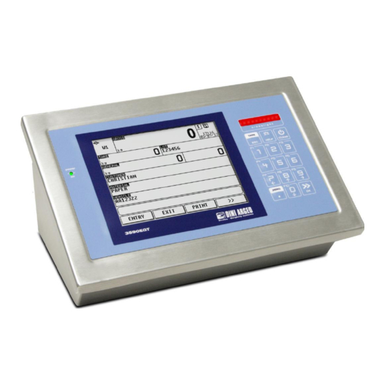
INDICATOR PARTS Figure 3. Front panel Part Description Touch screen Cross light (3 colors) Keyboard... -
Page 16: Display
INDICATOR PARTS Display The indicator presents 2 main screens, illustrated in the below scheme: Figure 4. First main screen Figure 5. Second main screen... - Page 17 INDICATOR PARTS Element Description Display indicators Active scale Touch to switch to the next scale Time and date Touch to change the date Weight value on the active scale Touch to tare the gross weight Tare value Touch to insert a preset tare Formula or production dosage progress bar Target value of the working formula if indicator is in dosage Total target of the production if the production is existed and indicator is out of dosage...
-
Page 18: Display Indicators
INDICATOR PARTS 4.1.1 Display Indicators Symbol Description The weight detected by the weighing system is near the zero, included within the interval of –1/4 and +1/4 of the scale division The weight is unstable A tare value has been acquired A preset tare value has been entered Active weighing range Locked keyboard... -
Page 19: Numeric Input
INDICATOR PARTS 4.1.2 Numeric input Screen Function Allows to insert a numeric value within the range. X ~ Y: valid range for the value to insert 0…9: numbers .: decimal point +/-: positive or negative sign / * - +: arithmetic operations C: clears all the value BkSp: backspace OK: exit saving the value... -
Page 20: Cross Light
INDICATOR PARTS Cross light The lights are managed in loading phase of manuals dosage the following way: Step Description Light The dosed weight is less than (target – tolerance weight) The dosed weight is inside tolerance range and lower than target. The frequency of the colours switching decreases when the target alternated –... -
Page 21: Manual Dosage Screen
INDICATOR PARTS FUNCTIONING: The function of light control is: The light are enabled depending on the weight reached during the manual dosage: WEIGHT TARGET-TOL. TARGET TARGET+TOL. GREEN YELLOW The operator gives the START impulse; the yellow light is enabled. The operator starts dosing in an approximate mode, in other words, at maximum speed. - Page 22 INDICATOR PARTS The following table describes the screen items. Item Description Weight type displayed by item 2 and unit of measure: DOSED in the loading phase, GROSS or NET in the unloading phase. Dosed weight/gross weight/net weight Dosage state bargraph. In the loading phase can have one of the following configurations: Weight out of tolerance and less than target Weight in tolerance and less than target...
-
Page 23: Main Functioning Description
MAIN FUNCTIONING DESCRIPTION All the functions of the indicator are available from the button in the second screen. The functions are divided into the following groups: Group Description Scale functions Operations to the weight (zeroing, tare, …) Printout Print functions management Generic functions Generic operations to the indicator (lock keyboard, calculator, …) Diagnostic... -
Page 24: Tare
MAIN FUNCTIONING DESCRIPTION If the weight on the scale is included in percentage Zeroing percentage with ZERO key), it is zeroed and the 0 indicator turns Tare 5.2.1 Semiautomatic tare Step Description Screen Press the key or touch on the weight area to tare the gross weight on the scale A message appears on the display... -
Page 25: Preset Tare
MAIN FUNCTIONING DESCRIPTION 5.2.2 Preset tare Step Description Screen Touch on the tare area Insert the preset tare value and confirm with the OK key The entered value is subtracted from the gross weight and the PT indicator turns on 5.2.3 Tare cancellation It’s possible to cancel the stored tare value in the following ways: By touching the weight area or by pressing the... -
Page 26: Input Texts
MAIN FUNCTIONING DESCRIPTION Input texts Step Description Screen Touch on the button to get access to the input texts Touch on the desired text to be changed Insert the content of the text and confirm with the OK button Touch on the ESC button to go back to the main screen... -
Page 27: Databases
MAIN FUNCTIONING DESCRIPTION Databases 5.4.1 Insertion Step Description Screen Touch on the button to get access to the desired database Select the desired position by touching the element or by touching the NEW button to insert an element in the first empty position Touch the first field to insert the content... - Page 28 MAIN FUNCTIONING DESCRIPTION The inserted element appears in the table with the first field value...
-
Page 29: Modification
MAIN FUNCTIONING DESCRIPTION 5.4.2 Modification Step Description Screen Touch the button to get access to the desired database Touch the element or the A..Z button to search the element to be updated Touch the desired field to be modified Insert the content of the field and confirm it with the OK button Repeat the operation for the desired fields to be updated and press the ... -
Page 30: Cancellation
MAIN FUNCTIONING DESCRIPTION 5.4.3 Cancellation Step Description Screen Touch the button to get access to the desired database Touch the element or the A..Z button to search the element to be deleted Touch the DELETE button Press the button to confirm or not the cancellation The element has been removed from the database... -
Page 31: Selection
MAIN FUNCTIONING DESCRIPTION 5.4.4 Selection Step Description Screen Touch the button in the first main screen to get access to the elements present into desired database Touch the desired element to select The description of selected element appears on the display... -
Page 32: Deselection
MAIN FUNCTIONING DESCRIPTION 5.4.5 Deselection Step Description Screen Touch the button in the first main screen to get access to the elements present into desired database A message indicates the index of the selected element. Touch the DESELECT button to deselect this element Press the button to confirm or not the deselection... -
Page 33: Insertion And Quick Selection Of The Temporary Record
MAIN FUNCTIONING DESCRIPTION 5.4.6 Insertion and quick selection of the temporary record Step Description Screen Touch the button in the first main screen to get access to the elements present into desired database Touch the element 0000 to insert the temporary element: previous... - Page 34 MAIN FUNCTIONING DESCRIPTION The description of element 0000 appears on the display...
-
Page 35: Alphanumeric Search
MAIN FUNCTIONING DESCRIPTION 5.4.7 Alphanumeric search Step Description Screen Touch the A..Z button in the database update/selection screen Insert the first characters of the element to search The table shows all the elements with the typed characters. Then touch the desired element... -
Page 36: Search By Element Index
MAIN FUNCTIONING DESCRIPTION 5.4.8 Search by element index Step Description Screen Touch the INDEX button in the database update/selection screen Insert the index of the desired element and confirm... -
Page 37: Printouts
MAIN FUNCTIONING DESCRIPTION Printouts The indicator has 27 print functions, each function has an associated format. When a function has been put into execution through the operation illustrated in the scheme, the associated format is sent to the print serial port. There are 30 available formats to associate to the print functions. -
Page 38: Setpoints
MAIN FUNCTIONING DESCRIPTION Setpoints To set the setpoints thresholds push the SETPOINT button on the second main screen. A screen like the of Figure 7 is displayed. In the example outputs 1, 2 and 3 are configured with hysteresys disabled Digital outputs). -
Page 39: Dosage
DOSAGE Automatic dosage of a product in loading 6.1.1 Dosage start With the system in the status of WAIT FOR START, by giving a START impulse, the indicator before enabling the dosage, checks that the signal coming from the scale’s load cell is stable. When one gives the START impulse the display shows the message WAIT STABLE WEIGHT for an instant and waits for the time set in the Wait stability time ( If the weight is unstable, the error is signalled and the display shows INSTABILITY ERROR. -
Page 40: End Of Loading Activity
DOSAGE AUTOMATIC FLY Flight wait Until the dosed weight DOSAGE (dosed >= Target is not in tolerance: OUT OF TOLERANCE – F) 6.1.3 End of loading activity Terminated the flight wait time phase ( Flight waiting time) if the tolerance checking is not enabled Enabling tolerance test) the loading phase terminates and the instrument switches to the total upload phase. -
Page 41: Complete Unloading
DOSAGE 6.1.4 Complete unloading Finally the instrument is ready for the UNLOADING phase. If in the formula is set unload type equal to Wait for confirmation the instrument displays the message WAIT UNLOAD START and waits of the START command by the user. If the unload type is set equal to Direct unload the instrument switches immediately to the unload phase. -
Page 42: Manual Dosage Of A Product In Loading
DOSAGE To execute the formula one should: a) select the formula b) put the initial tare on the plate, which must have a weight greater than 0.100kg and less than 1.000kg. c) Press the START button The instrument: d) starts to dose at maximum speed (approximate dosage). e) once the TARGET –... - Page 43 DOSAGE DOSAGE ACTIVE Low speed dosage MANUAL DOSING OUT OUT OF TOLERANCE (dosed weight >= TOLERANCE Target – S) DOSAGE ACTIVE Dosed weight MANUAL DOSING OK IN TOLLRANCE within tolerance range. With a START pulse switches to the total upload phase.
-
Page 44: Example Of A Manual Dosage
DOSAGE 6.2.1 Example of a manual dosage The formula Description TEST Scale Type MANUAL DOSAGE Target 10.000kg Slow weight 1.500kg Tolerance 0.200kg Unload type WAIT FOR CONFIRMATION Minimum tare 0.100kg Maximum 1.000kg It will execute a manual dosage of 10kg. To execute the formula one should: a) select the formula b) put the initial tare on the plate, which must have a weight greater than 0.100kg and less than... -
Page 45: Enabling Unloading Phase
DOSAGE shows the message: WAIT FILLING. The filling ends when the weight exceeds the FILLING END WEIGHT. The instrument is now ready to dose (START WEIGHT condition). If the condition is verified, the instrument starts the dosage at the maximum speed. 6.3.2 Enabling unloading phase The unloading phase is composed of the sub-phases shown in the following table. -
Page 46: Fill Checking
DOSAGE OUT OF TOLERANCE target WEIGHT OK IN TOLERANCE Dosed weight in tolerance and less or equal target WEIGHT OK IN TOLERANCE Dosed weight in OVER TARGET tolerance and greater than target TOLERANCE ERROR GENERIC ALARM Dosed weight out ... -
Page 47: Filling Phase
DOSAGE 6.3.5 Filling phase The filling phase is composed of the following sub-phases: Filling sub-phase Description Display message Active digital outputs WAIT FILLING FILLING Filling active Filling end If the setup parameter Filling end weight ( ) is set equal zero the filling phase terminates when the START command is given to the system. -
Page 48: Formula Execution Modes
DOSAGE Formula execution modes The instrument can execute the formula in 2 ways depending on how the system has been configured (see the Formula weight setting mode Formula weight Setting of the total weight 6.4.1 Formula weighs If the Formula weight functioning mode has been enabled in the set-up, the dosage is carried out as set in the formula. -
Page 49: Start Dosage Cycle
DOSAGE At the end, the instrument waits to receive the start of the new dosage, or, in case of various repetitions of the dosage cycle, restarts automatically with the following cycle. To pause a dosage under way, one should: press the external PAUSE button, which must be connected to the IN2 input of the instrument, or button. -
Page 50: Pause: Momentary Interruption Of The Dosage Cycle
DOSAGE 6.5.3 Pause: momentary interruption of the dosage cycle To pause the dosage, it is necessary to close for an instant the PAUSE input or push the PAUSE button. By carrying out this operation all the instrument’s outputs are disabled and the PAUSE message appears on the display. -
Page 51: Maximum Dosage Time
DOSAGE Formula Cycles = n executes n repetitions with automatic start 3) Confirm the number of set cycles by pressing the OK key 6.5.6 Maximum dosage time If the MAXIMUM DOSAGE TIME has been enabled ( Maximum time for the dosage) it is possible to check the dosage execution time. -
Page 52: Tolerance Expressed As Percentage Of The Weight
DOSAGE 6.6.2 Tolerance expressed as percentage of the weight During entering the formula, a tolerance can be entered expressed as a weight percentage value on the target weight entered in the formula, therefore the tolerance weight can be calculated dependently on the Target weight in order to increase the tolerance if the target is greater, and decrease it if the target is lower. -
Page 53: Production Program
DOSAGE A variable value from 1 to 100 represents the correction percentage which will be summed to the following cycle (for example, 50 causes the adding or the subtraction to the current flight weight of 50% of the previously calculated difference; in this way the correction will be buffered and less fast). Higher is the set value, and quicker will be the flight weight correction in the following dosage;... - Page 54 DOSAGE The dosed liquid is cleared The indicator turns on the dosage lights in active volume and dosage in fast volume (approximate) Once the TARGET VOLUME – FLIGHT VOLUME– SLOW VOLUME is reached, the instrument turns off the dosage light in fast volume (approximate) Once the TARGET VOLUME–...
- Page 55 DOSAGE The dosage filling step has Prsess the button, over the maximum filling time unloading filling when unload fillling step starts procedure will restart and if filling weight is ok, it will contineously excute the next step. ...
- Page 56 DOSAGE 6.11 Progressives 6.11.1 Additional value In MENUProgressivesAdditional value it’s possible to set a value of up to 6 digits, which is summed to each totalisation, and can be recalled in the printing. The same value is linked independently to three total types (PARTIAL, GENERAL, and GRAND TOTAL), in other words, it is possible to print three different values which will be cleared with the clearing of the relative total.
- Page 57 DECLARATION OF CONFORMITY This device conforms to the essential standards and norms relative to the applicable European regulations. The Declaration of conformity is available in the web site www.diniargeo.com. WARRANTY The TWO-YEAR warranty period begins on the day the instrument is delivered. It includes spare parts and labour for repairs at no charge if the INSTRUMENTS ARE RETURNED prepaid to the DEALER’S PLACE OF BUSINESS.
Need help?
Do you have a question about the EGT scale series and is the answer not in the manual?
Questions and answers