Table of Contents
Advertisement
Quick Links
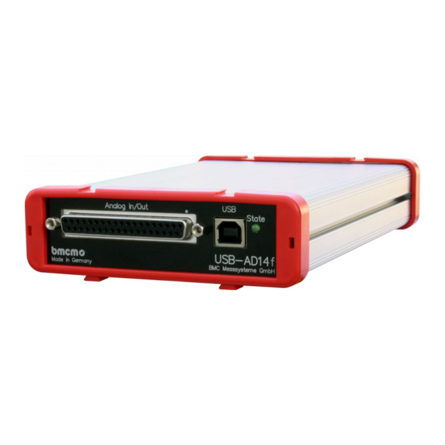
USB-AD14f
Data Acquisition System (USB)
Measurement & Control.
Super-Low Priced.
Record and output signals with the USB-AD14f.
The USB data acquisition system accomodated in
a stable aluminum housing is ideal for medium-
class applications impressing by universal appli-
cability and an excellent price-performance-ratio.
16 Analog Inputs.
20kHz. 14 Bit. 10V.
Voltage signals in the 10V range are connected
at 16 analog inputs. Sampling is done with 14 bit
resolution and 20kHz total sampling rate.
1 Analog Output. 12 Bit. 5V.
The 5V output can be used for analog control
with 12 bit accuracy.
8 Digital IN. 8 Digital OUT.
1 Counter.
Digital states are recorded or set at eight digital
inputs and outputs each. Digital inputs are
sampled time-synchronously with the analog
inputs. The USB-AD14f features a 16-bit counter
for the acquisition of counting pulses.
Functional diagram
Plug & Play.
The connection to the PC is realized via USB.
The USB-AD14f provides all typical USB
features (e.g. Plug&Play, Hot-Plug). Up to 127
devices can be connected and installed during
operation.
Powered by USB.
The device is supplied with power via the USB
interface. This reduces cabling efforts to a
minimum and makes mobile measurements a lot
easier.
Open for Everyone.
Widely supported: The data acquisition system
can be used under Windows
as under Mac OS X, Free BSD, and Linux. The
complete software for installation and program-
ming of the USB-AD14f is included for free.
NextView
4. Try for Free.
®
The DAQ system is supported by NextView
the software for data acquisition and analysis. A
fully functional 30-day trial is included with
delivery to directly test the functionality of the
USB-AD14f.
Accessory.
Makes Everything so Easy.
Use the demo board ZU-DBD featuring various
operating controls and sensors to generate 16
analog signals and record them with the USB data
acquisition system.
®
XP/7/8/10 as well
4,
®
Advertisement
Table of Contents

Related Manuals for bmcm USB-AD14f


Summary of Contents for bmcm USB-AD14f
- Page 1 8 Digital IN. 8 Digital OUT. complete software for installation and program- 1 Counter. ming of the USB-AD14f is included for free. Digital states are recorded or set at eight digital inputs and outputs each. Digital inputs are sampled time-synchronously with the analog inputs.
- Page 2 Start-up Procedure Install the bmcm driver package (see chapter 5.1.1). Plug the red frames onto the short sides of the device with the feet looking downward as to be seen in the product picture. Connect one end of the USB cable to the device and the other to the USB-interface of the PC and start the Plug&Play installation (see chapter 5.1.2).
- Page 3 4 Interfacing Examples for the Digital Lines of the USB-AD14f The following basic connection examples demonstrate the use of the digital inputs and outputs and the connection of a counter to the USB-AD14f. The pin assignment of the 25-pin D-Sub female connector is described in chapter 3.
- Page 4 USB-AD14f 4.1.2 Connecting a Push-Button / Switch Please make sure to use a push-button with debounce protection, because otherwise several pulses might be recorded. The 3.9k pull-down resistor is absolutely necessary to create a defined low signal! 4.1.3 Connecting a Voltage Divider...
- Page 5 Relay cards featuring 8 outputs are available at bmcm. 4.2.3 Connecting a Lamp A transistor can be used to switch higher loads. The selected transistor must comply with the maximum switchable current.
- Page 6 Collection" CD included with delivery. When inserting the CD, a CD starter opens automatically (otherwise: start openhtml.exe). Change to the product page of the USB-AD14f by selecting the entry "Products" in the CD starter and then the hardware ("USB-AD14f") listed under the interface "USB".
- Page 7 XP: Start / Control Panel / System / TAB "Hardware" / button "Device Manager" Double click the "USB-AD14f" to show the properties of the USB data acquisition system. For general information, existing device conflicts and possible sources of error, see TAB "General".
- Page 8 The gain is adjusted to even values. Therefore, only 16000 values (for 14 bit) of the full range of the converter are used. As a result, the measuring ranges are slightly larger (e.g. 10.24V) than the indicated measuring ranges so that overranges can be recognized. The AD converter of the USB-AD14f has a code noise of up to 2 LSB. ...
Need help?
Do you have a question about the USB-AD14f and is the answer not in the manual?
Questions and answers