
Related Manuals for Gemalto Cinterion ELS61T-US


Summary of Contents for Gemalto Cinterion ELS61T-US
- Page 1 ® Cinterion LTE Terminals Hardware Interface Description Version: DocId: ELSxT_HID_v04 GEMALTO.COM/M2M...
- Page 2 Copyright © 2018, Gemalto M2M GmbH, a Gemalto Company Trademark Notice Gemalto, the Gemalto logo, are trademarks and service marks of Gemalto and are registered in certain countries. Microsoft and Windows are either registered trademarks or trademarks of Microsoft Corpora- tion in the United States and/or other countries.
-
Page 3: Table Of Contents
® Page 3 of 102 Cinterion LTE Terminals Hardware Interface Description Contents Contents Document History ...................... 8 Introduction ....................... 10 Related Documents ..................11 Terms and Abbreviations ................. 11 Regulatory and Type Approval Information ............. 13 1.3.1 Directives and Standards..............13 1.3.2 Safety Precautions................ - Page 4 Mechanical Dimensions ................... 61 Mounting the LTE Terminals ................64 Packaging ......................65 Full Type Approval....................66 Gemalto M2M Reference Setup ..............66 Restrictions ...................... 67 CE Conformity....................67 EMC ......................... 67 Compliance with FCC and IC Rules and Regulations ........68 Compliance with Japanese Rules and Regulations .........
- Page 5 ® Page 5 of 102 Cinterion LTE Terminals Hardware Interface Description Contents Appendix B: Ethernet Setup and Usage ..............95 Connection Setup .................... 95 Connection Usage ................... 97 9.2.1 Access LTE Terminal via Telnet (or SSH) .......... 97 9.2.2 Access LTE Terminal via FTP ............98 9.2.3 Security Notes..................
- Page 6 ® Page 6 of 102 Cinterion LTE Terminals Hardware Interface Description Tables Tables ® Table 1: Cinterion LTE Terminals overview ..............10 Table 2: Terms and abbreviations................. 11 Table 3: Directives ......................13 Table 4: Standards of North American type approval ........... 13 Table 5: Standards of European type approval.............
- Page 7 ® Page 7 of 102 Cinterion LTE Terminals Hardware Interface Description Figures Figures Figure 1: Product label of ELS61T-E................18 Figure 2: Product Label of ELS61T-AUS ............... 18 Figure 3: Product label of ELS61T-US ................19 Figure 4: LTE Terminals 3D view ................... 24 Figure 5: Block diagram ....................
-
Page 8: Document History
® Page 8 of 102 Cinterion LTE Terminals Hardware Interface Description 0 Document History Document History ® Preceding document: "Cinterion LTE Terminals Hardware Interface Description" Version 03a ® New document: "Cinterion LTE Terminals Hardware Interface Description" Version 04 Chapter What is new Product ELS61T-E2 added and adapted document accordingly 3.6.2.2, Added description and configuration of the Audio Codec Board... - Page 9 ® Page 9 of 102 Cinterion LTE Terminals Hardware Interface Description 0 Document History Revised Table 14 regarding digital audio signal names Revised Table 17 regarding IGT_IN signal 3.9.1, 3.9.2, Revised chapters regarding “auto ignition” 3.9.3, 3.12 Removed IGT_IN from Table 19 4.2.1 Removed IGT_IN from...
-
Page 10: Introduction
LTE Terminals. It specifies standards pertaining to wireless applications 1. The document is effective only if listed in the appropriate Release Notes as part of the technical docu- mentation delivered with your Gemalto M2M product. ELSxT_HID_v04 2018-09-04 ... -
Page 11: Related Documents
Terminals easily as GSM/GPRS/UMTS/LTE modems. Related Documents AT Command Set for your LTE Terminal product Release Notes for your LTE Terminal product To visit the Gemalto M2M GmbH Website please use the following link: http://www.gemalto.com/m2m/ Terms and Abbreviations Table 2: Terms and abbreviations... - Page 12 ® Page 12 of 102 Cinterion LTE Terminals Hardware Interface Description 1.2 Terms and Abbreviations Table 2: Terms and abbreviations Abbreviation Description Ignition International Standards Organization International Telecommunications Union kbps kbits per second Low voltage Directive Mbps Mbits per second Microprocessor Controll Unit Machine Machine Interface Mobile Originated...
-
Page 13: Regulatory And Type Approval Information
® Page 13 of 102 Cinterion LTE Terminals Hardware Interface Description 1.3 Regulatory and Type Approval Information Regulatory and Type Approval Information 1.3.1 Directives and Standards LTE Terminals have been designed to comply with the directives and standards listed below Table 3: Directives 2014/53/EU Directive of the European Parliament and of the council of 16 April 2014... -
Page 14: Table 6: Standards Of Japanese Type Approval
® Page 14 of 102 Cinterion LTE Terminals Hardware Interface Description 1.3 Regulatory and Type Approval Information Table 5: Standards of European type approval Draft ETSI EN 301 489-52 Electromagnetic Compatibility (EMC) standard for radio equipment and V1.1.0 services; Part 52: Specific conditions for Cellular Communication Mobile and portable (UE) radio and ancillary equipment;... -
Page 15: Table 8: Standards Of The Ministry Of Information Industry Of The People's Republic
® Page 15 of 102 Cinterion LTE Terminals Hardware Interface Description 1.3 Regulatory and Type Approval Information Table 8: Standards of the Ministry of Information Industry of the People’s Republic of China SJ/T 11363-2006 “Requirements for Concentration Limits for Certain Hazardous Sub- stances in Electronic Information Products”... -
Page 16: Safety Precautions
Failure to comply with these precautions violates safety standards of design, manufacture and intended use of the product. Gemalto M2M GmbH assumes no liability for customer’s failure to comply with these precautions. - Page 17 ® Page 17 of 102 Cinterion LTE Terminals Hardware Interface Description 1.3 Regulatory and Type Approval Information IMPORTANT! Cellular terminals or mobiles operate using radio signals and cellular networks. In that case connections cannot be guaranteed at all times under all conditions. There- fore, you should never rely solely upon any wireless device for essential communi- cations, for example emergency calls.
-
Page 18: Product Label
® Page 18 of 102 Cinterion LTE Terminals Hardware Interface Description 1.4 Product Label Product Label The label fixed to the bottom of a LTE Terminal comprises the following information. Figure 1: Product label of ELS61T-E The label for ELS61T-E2 is similar to the label of ELS61T-E (Figure 1), but with a different pro- duct name (ELS61T-E2) and part number (S30960-S2751-A200). -
Page 19: Table 10: Lte Terminals Label Information
FCC ID for LTE module contained in LTE Terminal IC ID for LTE module contained in LTE Terminal Manufacturer code Power supply unit ratings Manufacturer code (2D) Contact address: Gemalto M2M GmbH, Werinherstrasse 81, 81541 Munich, Germany. ELSxT_HID_v04 2018-09-04 Confidential / Preliminary... -
Page 20: Product Concept
® Page 20 of 102 Cinterion LTE Terminals Hardware Interface Description 2 Product Concept Product Concept Key Features at a Glance Feature Implementation General ® Incorporates Cinterion The LTE module handles all signal and data processing within the LTE Ter- LTE module minals. - Page 21 ® Page 21 of 102 Cinterion LTE Terminals Hardware Interface Description 2.1 Key Features at a Glance Feature Implementation Output power (according Class 4 (+33dBm ±2dB) for EGSM900 to Release 99, V5) Class 1 (+30dBm ±2dB) for GSM1800 depending on frequency Class E2 (+27dBm ±...
- Page 22 Point-to-point MT and MO • Cell broadcast • Text and PDU mode Software AT commands Hayes 3GPP TS 27.007, TS 27.005, Gemalto M2M Java™ Open Platform Java™ Open Platform with (ESLS61-X only) • Java™ profile IMP-NG & CLDC 1.1 HI •...
- Page 23 ® Page 23 of 102 Cinterion LTE Terminals Hardware Interface Description 2.1 Key Features at a Glance Feature Implementation GPIO connector 20-pin (8-pin and 12-pin) header with GPIO interface, external power sup- ply, serial interface ASC1, ADC, DAI/PCM, SPI and I²C, depending on vari- Ethernet 8-pole RJ-45 Ethernet connector Support for Power over Ethernet (PoE)
-
Page 24: Interface Description
® Page 24 of 102 Cinterion LTE Terminals Hardware Interface Description 3 Interface Description Interface Description Overview LTE Terminals provide the following interfaces for power supply, antenna, SIM card and data transfer: Table 11: LTE Terminals‘ interfaces Description 6-pin Western connector (female) for power supply, ignition, power down signal 8-pin (female) RJ-45 Ethernet connector 9-pin (female) D-sub connector (RS-232 interface) SMA connector (female) for GPS antennas (for future use, currently not available) -
Page 25: Block Diagram
® Page 25 of 102 Cinterion LTE Terminals Hardware Interface Description 3.2 Block Diagram Block Diagram Figure 5 shows a block diagram of a sample configuration that incorporates a LTE Terminal and typical accessories. Main antenna Antennas RF antenna Diversity antenna interface RS-232 driver... -
Page 26: Terminal Circuit
® Page 26 of 102 Cinterion LTE Terminals Hardware Interface Description 3.3 Terminal Circuit Terminal Circuit Figure 6 shows a general LTE Terminal block diagram that includes all variants. Vreg WD_RETRIG (GPIO8) (Hardware ) Level - Watchdog shifter VCCref Driver GPIO Supply bidirect. -
Page 27: Operating Modes
® Page 27 of 102 Cinterion LTE Terminals Hardware Interface Description 3.4 Operating Modes Operating Modes The table below briefly summarizes the various operating modes referred to in the following chapters. Table 12: Overview of operating modes Mode Function Normal operation UMTS / HSPA / LTE Power saving set automatically when no call is in prog- SLEEP... -
Page 28: Interface
® Page 28 of 102 Cinterion LTE Terminals Hardware Interface Description 3.5 RS-232 Interface RS-232 Interface The interface is implemented as a serial asynchronous transmitter and receiver conforming to ITU-T V.24 Interchange Circuits DCE. It is configured for 8 data bits, no parity and 1 stop bit, and can be operated at bit rates from 1200bps to 921kbps. -
Page 29: Gpio Interface
® Page 29 of 102 Cinterion LTE Terminals Hardware Interface Description 3.6 GPIO Interface Hardware handshake using the RTS0 and CTS0 signals and XON/XOFF software flow control are supported. In addition, the modem control signals DTR0, DSR0, DCD0 and RING0 are available. The mo- dem control signal RING0 (Ring Indication) can be used to indicate, to the cellular device ap- plication, that a call or Unsolicited Result Code (URC) is received. -
Page 30: Figure 9: Els61T-E: Gpio Connectors (8-Pin And 12-Pin)
® Page 30 of 102 Cinterion LTE Terminals Hardware Interface Description 3.6 GPIO Interface ELS61T-E: GPIO6 GPIO7 GPIO8 GPIO11 VCCref TXD1/ RXD1/ CTS1 RTS1 SPI_MISO SPI_MOSI (RS232)/ (RS232) SPI_CS GPIO12 GPIO13 GPIO22/ GPIO23 +5Vout DSR0/ I2CDAT I2CCLK GPIO20 GPIO21 ADC1_IN/ SPI_CLK Figure 9: ELS61T-E: GPIO connectors (8-pin and 12-pin) ELS61T-E2:... -
Page 31: Table 14: Gpio Connector Pin Availability And Alternate Pin Functionalities
® Page 31 of 102 Cinterion LTE Terminals Hardware Interface Description 3.6 GPIO Interface ELS31T-V/J: GPIO6 GPIO7 GPIO8 VCCref TXD1 RXD1 CTS1 RTS1 (RS232)/ (RS232/ GPIO22 GPIO23 +5Vout DSR0/ I2CDAT I2CCLK GPIO20 GPIO21 ADC1_IN n/a: not applicable Figure 11: ELS31T-V/J: GPIO connectors (8-pin and 12-pin) The following Table 14 shows the availability of the GPIO connector pins for various LTE Ter-... -
Page 32: Serial Interface Asc1
® Page 32 of 102 Cinterion LTE Terminals Hardware Interface Description 3.6 GPIO Interface Table 14: GPIO connector pin availability and alternate pin functionalities Signal Comment ELS61T- ELS61T- ELS61T- ELS61T- ELS31 T-V/J TXD1 or Configurable via AT command, TXD1 / TXD1 / TXD1 /... -
Page 33: Digital Audio Interface (Els61T-E2)
® Page 33 of 102 Cinterion LTE Terminals Hardware Interface Description 3.6 GPIO Interface 3.6.2 Digital Audio Interface (ELS61T-E2) Four pins at the LTE Terminals‘ GPIO connector can be configured as digital audio interface (DAI). The DAI can be used to connect audio devices capable of pulse code modulation (PCM). The PCM functionality allows for the use of an external codec like the W681360. -
Page 34: Figure 13: Block Circuit For Dai/Pcm To Analog Converter
® Page 34 of 102 Cinterion LTE Terminals Hardware Interface Description 3.6 GPIO Interface 3.6.2.1 Solutions for the Digital Audio Interface (DAI/PCM) The Digital Audio Interface is only supported in ELS61T-E2. Figure 13 Figure 14 show an example of using the digital audio interface of the LTE Terminal. The below mentioned sample Nuvoton codec W681360 can be replaced with a DSP. -
Page 35: Figure 15: Audio Codec Board
® Page 35 of 102 Cinterion LTE Terminals Hardware Interface Description 3.6 GPIO Interface single channel PCM CODEC chip (AK2300), has a fixed terminal block (green connector) in order to connect easily to the Terminal ELS61T-E2 and a 3.5 mm plug connector for the head- phone. - Page 36 • The configuration is non-volatile and becomes active after a module restart. If the DAI Interface is active, the Activity LED is on. For more information and example Java Midlets, please visit Developer Community at http://developer.gemalto.com ELSxT_HID_v04 2018-09-04 Confidential / Preliminary...
-
Page 37: C Interface
® Page 37 of 102 Cinterion LTE Terminals Hardware Interface Description 3.6 GPIO Interface 3.6.3 C Interface Two lines of the LTE Terminals‘ GPIO connector are I C lines. I C is a serial, 8-bit oriented data transfer bus for bit rates up to 400kbps in Fast mode. It consists of two lines, the serial data line I2CDAT and the serial clock line I2CCLK. -
Page 38: Spi Interface
® Page 38 of 102 Cinterion LTE Terminals Hardware Interface Description 3.6 GPIO Interface 3.6.4 SPI Interface For ELS61T-X Terminals four dedicated pins of the GPIO connector can be configured as Se- rial Peripheral Interface (SPI). The SPI is a synchronous serial interface for control and data transfer between LTE Terminals and the external application. -
Page 39: Pwm Interface
® Page 39 of 102 Cinterion LTE Terminals Hardware Interface Description 3.6 GPIO Interface 3.6.5 PWM Interface The GPIO6 and GPIO7 pins at the GPIO connector can be configured as Pulse Width Modu- lation signals PWM1 and PWM2 by AT^SCFG command - see [1]. The PWM interface lines are output lines and can be used, for example, to connect buzzers. -
Page 40: Ethernet Interface
® Page 40 of 102 Cinterion LTE Terminals Hardware Interface Description 3.7 Ethernet Interface Ethernet Interface The Ethernet interface is available on all LTE Terminals. . 1 2 3 4 5 6 7 8 Green LED (Link/Activity) Figure 17: 8-pole RJ-45 Ethernet connector (female) Table 16: Female 8-pole RJ-45 Ethernet connector Signal name Comment... -
Page 41: Power Supply
Figure 18: 6-pole Western jack for power supply, ignition, reset, typical connection Mains adapter: If it fits into the design of your application we recommend the plug-in supply unit used with the type approved Gemalto M2M reference setup. Ordering information can be found Chapter 7. -
Page 42: Power Up/Power Down Scenarios
® Page 42 of 102 Cinterion LTE Terminals Hardware Interface Description 3.9 Power Up/Power Down Scenarios nal connection between IGT_IN pin and PLUS pin.LTE Terminals don’t support the IGT_IN function. Note that if employing PoE for LTE Terminals, the module will restart automatically after a normal shutdown. -
Page 43: Turn Lte Terminals Off
® Page 43 of 102 Cinterion LTE Terminals Hardware Interface Description 3.9 Power Up/Power Down Scenarios Emergency restart: • Finally, LTE Terminals can be reset/restarted in the event of software hang-ups etc. by applying a voltage >8V to the RST_IN pin (pin 3) for more than 10ms. The RST_IN signal then restarts the LTE Terminals. -
Page 44: Automatic Thermal Shutdown
® Page 44 of 102 Cinterion LTE Terminals Hardware Interface Description 3.10 Automatic thermal shutdown 3.10 Automatic thermal shutdown An on-board NTC measures the temperature of the built-in LTE module. If over- or under-tem- perature is detected on the module the LTE Terminals automatically shut down to avoid thermal damage to the system. -
Page 45: Sim Interface
® Page 45 of 102 Cinterion LTE Terminals Hardware Interface Description 3.13 SIM Interface 3.13 SIM Interface The SIM interface is intended for 1.8V and 3V SIM cards in accordance with GSM 11.12 Phase 2. The card holder is a five wire interface according to GSM 11.11. A sixth pin has been added to detect whether or not a SIM card is inserted. -
Page 46: Status Leds
® Page 46 of 102 Cinterion LTE Terminals Hardware Interface Description 3.14 Status LEDs 3.14 Status LEDs LTE Terminals have two LEDs indicating its operating states through the semitransparent cas- ing: • A green LED indicates whether the LTE Terminals are ready to operate and reports certain watchdog operations. -
Page 47: Rf Antenna Interface
® Page 47 of 102 Cinterion LTE Terminals Hardware Interface Description 3.15 RF Antenna Interface 3.15 RF Antenna Interface The external RF antennas are connected via the LTE Terminals’s female SMA connectors that is also the antenna reference point (ARP). Figure 21: Antenna connectors The system impedance is 50 . -
Page 48: Electrical And Environmental Characteristics
® Page 48 of 102 Cinterion LTE Terminals Hardware Interface Description 4 Electrical and Environmental Characteristics Electrical and Environmental Characteristics Absolute Maximum Ratings Table 19: Absolute maximum ratings Parameter Port / Description Min. Max. Unit Supply voltage PLUS Input voltage for on/off RST_IN control lines RS-232 input voltage... -
Page 49: Electrical Specifications Of The Application Interface
® Page 49 of 102 Cinterion LTE Terminals Hardware Interface Description 4.2 Electrical Specifications of the Application Interface Electrical Specifications of the Application Interface 4.2.1 On/Off Control Table 21: On/Off control line specifications Parameter Description Conditions Min. Max. Unit Input voltage active high high RST_IN... -
Page 50: Gpio Interface
® Page 50 of 102 Cinterion LTE Terminals Hardware Interface Description 4.2 Electrical Specifications of the Application Interface 4.2.4 GPIO Interface Table 23: GPIO interface specifications (requirements) Function Signal name Signal form and level Comment 8-pin, 12- GPIO 6-8 max = 0.1V at I = 100µA If unused keep lines pin connec- GPIO 11-13... -
Page 51: Ethernet Interface
® Page 51 of 102 Cinterion LTE Terminals Hardware Interface Description 4.2 Electrical Specifications of the Application Interface Table 23: GPIO interface specifications (requirements) Function Signal name Signal form and level Comment 8-pin, 12- I2CDAT Open drain IO According to the I C Bus pin connec- min = 0.3V at I = -3mA... -
Page 52: Maximum Power Supply Ratings
® Page 52 of 102 Cinterion LTE Terminals Hardware Interface Description 4.3 Maximum Power Supply Ratings Maximum Power Supply Ratings Table 24: Power supply specifications Para- Description Conditions Typical Unit meter ELS61 ELS61 ELS61 ELS31 ELS31 T-E/E2 T-US T-AUS Allowed voltage ripple Power control 0.3 V PLUS... - Page 53 ® Page 53 of 102 Cinterion LTE Terminals Hardware Interface Description 4.3 Maximum Power Supply Ratings Table 24: Power supply specifications Para- Description Conditions Typical Unit meter ELS61 ELS61 ELS61 ELS31 ELS31 T-E/E2 T-US T-AUS Peak supply current Power control 1830 - mA PLUS...
- Page 54 ® Page 54 of 102 Cinterion LTE Terminals Hardware Interface Description 4.3 Maximum Power Supply Ratings Table 24: Power supply specifications Para- Description Conditions Typical Unit meter ELS61 ELS61 ELS61 ELS31 ELS31 T-E/E2 T-US T-AUS HSPA DATA - mA PLUS Band IV;...
- Page 55 ® Page 55 of 102 Cinterion LTE Terminals Hardware Interface Description 4.3 Maximum Power Supply Ratings Table 24: Power supply specifications Para- Description Conditions Typical Unit meter ELS61 ELS61 ELS61 ELS31 ELS31 T-E/E2 T-US T-AUS LTE DATA - mA PLUS Band 18, 23dBm @30V @57V...
-
Page 56: Operating Temperatures
® Page 56 of 102 Cinterion LTE Terminals Hardware Interface Description 4.4 Operating Temperatures Operating Temperatures Table 25: Temperature characteristics Parameter Typical Unit Normal operation °C Extended operation -40 to -30 +85 to +90 °C Automatic thermal shutdown <-40 >+90 °C Thermal resistance (R 2G operation (with P... -
Page 57: Antenna Interface
® Page 57 of 102 Cinterion LTE Terminals Hardware Interface Description 4.5 Antenna Interface Antenna Interface Table 26 lists RF antenna interface specifications for the LTE Terminals. Please note that the specified conditions may not apply to or be supported by all terminals. Table 26: RF Antenna interface GSM / UMTS / LTE Parameter Conditions... - Page 58 ® Page 58 of 102 Cinterion LTE Terminals Hardware Interface Description 4.5 Antenna Interface Table 26: RF Antenna interface GSM / UMTS / LTE Parameter Conditions Min. Typical Max. Unit LTE AWS Band 4 (ch. band- RF Power @ ARP with 50Ω width 5MHz;...
- Page 59 ® Page 59 of 102 Cinterion LTE Terminals Hardware Interface Description 4.5 Antenna Interface Table 26: RF Antenna interface GSM / UMTS / LTE Parameter Conditions Min. Typical Max. Unit RF Power @ GPRS, 1 TX GSM 850 / E-GSM 900 GSM 1800 / GSM 1900 with 50Ohm Load,...
-
Page 60: Storage Conditions
® Page 60 of 102 Cinterion LTE Terminals Hardware Interface Description 4.6 Storage Conditions Storage Conditions Table 27: Storage conditions Type Condition Unit Reference Air temperature: °C ETS 300 019-2-1: T1.2, IEC 60068-2-1 Ab High ETS 300 019-2-1: T1.2, IEC 60068-2-2 Bb Humidity relative: High 90 at 30°C... -
Page 61: Mechanics, Mounting And Packaging
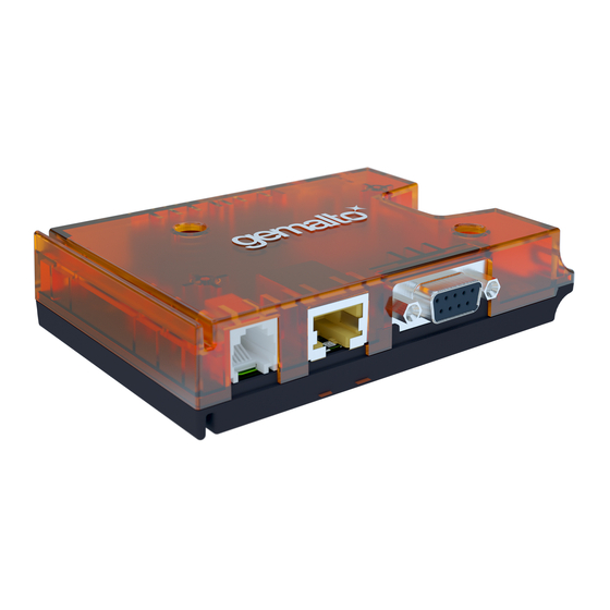
® Page 61 of 102 Cinterion LTE Terminals Hardware Interface Description 5 Mechanics, Mounting and Packaging Mechanics, Mounting and Packaging Mechanical Dimensions Figure 22 shows a 3D view of the LTE Terminal and provides an overview of the mechanical dimensions of the board. For further details see Figure 23 Figure 24. -
Page 62: Figure 23: Lte Terminals Mechanical Dimensions
® Page 62 of 102 Cinterion LTE Terminals Hardware Interface Description 5.1 Mechanical Dimensions Figure 23: LTE Terminals mechanical dimensions ELSxT_HID_v04 2018-09-04 Confidential / Preliminary... -
Page 63: Figure 24: Lte Terminals Exploded View
® Page 63 of 102 Cinterion LTE Terminals Hardware Interface Description 5.1 Mechanical Dimensions Figure 24: LTE Terminals exploded view ELSxT_HID_v04 2018-09-04 Confidential / Preliminary... -
Page 64: Mounting The Lte Terminals
® Page 64 of 102 Cinterion LTE Terminals Hardware Interface Description 5.2 Mounting the LTE Terminals Mounting the LTE Terminals There are a number of ways to mount the LTE Terminals: • LTE Terminals can be attached to a rail installation or other surface using the two provided screw holes for screws, e.g., size M3. -
Page 65: Packaging
® Page 65 of 102 Cinterion LTE Terminals Hardware Interface Description 5.3 Packaging Packaging LTE Terminals come in terminal boxes: • Terminal box size: 191mm x 143mm x 44mm. ELSxT_HID_v04 2018-09-04 Confidential / Preliminary... -
Page 66: Full Type Approval
LTE Terminals Hardware Interface Description 6 Full Type Approval Full Type Approval Gemalto M2M Reference Setup The Gemalto M2M reference setup submitted to type approve LTE Terminals consists of the following components: • LTE Terminal with approved LTE module •... -
Page 67: Restrictions
® Page 67 of 102 Cinterion LTE Terminals Hardware Interface Description 6.2 Restrictions Restrictions Later enhancements and modifications beyond the certified configuration require extra approv- als. Each supplementary approval process includes submittal of the technical documentation as well as testing of the changes made. •... -
Page 68: Compliance With Fcc And Ic Rules And Regulations
• Consult the dealer or an experienced radio/TV technician for help. Changes or modifications made to this equipment not expressly approved by Gemalto M2M may void the FCC authorization to operate this equipment. This device contains LTE, UMTS, GSM and GPRS class functions in the 700 (Bd28), 800/850 (Bd6, Bd18, Bd19), 900, 1800 and 2100MHz bands that are not operational in U.S. - Page 69 ® Page 69 of 102 Cinterion LTE Terminals Hardware Interface Description 6.5 Compliance with FCC and IC Rules and Regulations Notes (IC): (EN) This Class B digital apparatus complies with Canadian ICES-003 and RSS-210. Opera- tion is subject to the following two conditions: (1) this device may not cause interference, and (2) this device must accept any interference, including interference that may cause undesired operation of the device.
-
Page 70: Compliance With Japanese Rules And Regulations
® Page 70 of 102 Cinterion LTE Terminals Hardware Interface Description 6.6 Compliance with Japanese Rules and Regulations Compliance with Japanese Rules and Regulations The ELS31T-J reference application described in Section 6.1 complies with the requirements of the Japanese "Telecommunications Business Law" and "Ordinance Concerning Technical Regulations Conformity Certification of Specified Radio Equipment"... -
Page 71: List Of Parts And Accessories
7 List of Parts and Accessories List of Parts and Accessories Table 28: List of parts and accessories Description Supplier Ordering information LTE Terminals Gemalto M2M Ordering number ELS61T-E: L30960-N2751-A100 ELS61T-E2: L30960-N2751-A200 ELS61T-AUS: L30960-N2753-A100 ELS61T-US: L30960-N2752-A100 ELS31T-J: L30960-N2755-A100 ELS31T-V: L30960-N2754-A100... - Page 72 ® Page 72 of 102 Cinterion LTE Terminals Hardware Interface Description 7 List of Parts and Accessories Table 28: List of parts and accessories Description Supplier Ordering information 8-pin and 12-pin header GPIO con- Weidmueller Ordering number (12-pin): 1277510000 nector (female plug) for GPIO inter- Ordering number (8-pin): 1277480000 face Weidmüller Interface GmbH &...
-
Page 73: Appendix A: (Hardware) Watchdog
® Page 73 of 102 Cinterion LTE Terminals Hardware Interface Description 8 Appendix A: (Hardware) Watchdog Appendix A: (Hardware) Watchdog The watchdog is part of the LTE Terminals and connected to the LTE module itself (see also Figure 6). It can be used to •... -
Page 74: Reset Conditions
® Page 74 of 102 Cinterion LTE Terminals Hardware Interface Description 8.1 Reset Conditions Reset Conditions The watchdog implements three conditions, under which a reset of the module is automatically performed: • Repetitive: A module reset is performed frequently and repetitive. This reset condition can be used to force the module to reconnect to the mobile network once in a while. -
Page 75: Reset Delay
® Page 75 of 102 Cinterion LTE Terminals Hardware Interface Description 8.2 Restart Conditions 8.1.2 Reset Delay The watchdog implements a protection mechanism to prevent too frequent module resets. When the delayed reset mechanism is enabled, the watchdog will start its activity only after the specified amount of time, MIN_START_TIME. -
Page 76: Complete Watchdog Configuration
® Page 76 of 102 Cinterion LTE Terminals Hardware Interface Description 8.3 Complete Watchdog Configuration Complete Watchdog Configuration The complete hardware watchdog functionality can be configured via the TXD0 line of the serial interface ASC0 as described in this section. The watchdog listens on the TXD0 line exclusively at the low baudrate 1200bps. - Page 77 ® Page 77 of 102 Cinterion LTE Terminals Hardware Interface Description 8.3 Complete Watchdog Configuration The following watchdog configuration commands are available: • Watchdog on/off - see Section 8.3.1.1 • Test mode - see Section 8.3.1.2 • Repetitive module reset - see Section 8.3.1.3 •...
- Page 78 ® Page 78 of 102 Cinterion LTE Terminals Hardware Interface Description 8.3 Complete Watchdog Configuration 8.3.1.2 Test Mode TEST_MODE Command Parameter <on|off> Type Boolean Range 0: Off (Exit test mode) 1: On (Enter test mode) Default 0: Off Non-volatile TEST_MODE Example ,0,0 // Exit test mode...
- Page 79 ® Page 79 of 102 Cinterion LTE Terminals Hardware Interface Description 8.3 Complete Watchdog Configuration 8.3.1.4 UART Reset RST_UART Command Parameter <timeout> Type Milliseconds Range 0 .. 2 Default 0: Feature is disabled Non-volatile Example WD=RST_UART,600000,6 // Resets the module if there was no activity on the RXD0 line for 10 minutes This command configures a module reset, if no UART activity from the module was observed for the specified amount of time - RST_UART.
- Page 80 ® Page 80 of 102 Cinterion LTE Terminals Hardware Interface Description 8.3 Complete Watchdog Configuration 8.3.1.6 C Reset RST_I2C Command Parameter <timeout> Type Milliseconds Range 0 .. 2 Default 0: Feature is disabled Non-volatile Example WD=RST_I2C,600000,6 // Resets the module if there was no keep alive signal received at the I C bus address 0x09 for 10 minutes.
- Page 81 ® Page 81 of 102 Cinterion LTE Terminals Hardware Interface Description 8.3 Complete Watchdog Configuration 8.3.1.7 Restart Delay MIN_START_TIME Command Parameter <timeout> Type Milliseconds Range 0 .. 2 Default 18000000ms (30 minutes) Non-volatile Example WD=MIN_START_TIME,18000000,9 // Prevents module resets for 30 minutes after each module startup, and after the watchdog becomes active This command configures the MIN_START_TIME timeout value.
- Page 82 ® Page 82 of 102 Cinterion LTE Terminals Hardware Interface Description 8.3 Complete Watchdog Configuration 8.3.1.8 Always On Command ALWAYS_ON Parameter <timeout> Type Milliseconds Range 0 .. 2 Default 0: Feature is disabled Non-volatile Example WD= ALWAYS_ON,60000,6 // Observes the module and restarts it 60 seconds after it has been turned off This command configures the on/off-state observation of the module by specifying a timeout value for ALWAYS_ON.
- Page 83 ® Page 83 of 102 Cinterion LTE Terminals Hardware Interface Description 8.3 Complete Watchdog Configuration 8.3.1.10 Change the Watchdog‘s I C Address Command I2C_ADDR Parameter <address> Type Number Range 1-127 Default 106 (0x6A) Non-volatile Example WD= I2C_ADDR,87,15 // Changes the I C address to 87d (0x57) The watchdog‘s I C slave address can be changed to any 7-bit address.
- Page 84 ® Page 84 of 102 Cinterion LTE Terminals Hardware Interface Description 8.3 Complete Watchdog Configuration 8.3.1.11 Set GPIO Direction Command GPIO_DIR Parameter <pin-config> Type Number Range 0-1023 Default 0 (0x000, 0000000000b) Non-volatile Example WD= GPIO_DIR,682,16 // Sets the GPIOs alternating to output and input (binary value: 1010101010b) This command configures the input/output direction of level-shifters to the module‘s externally available GPIO pins.
- Page 85 ® Page 85 of 102 Cinterion LTE Terminals Hardware Interface Description 8.3 Complete Watchdog Configuration 8.3.1.12 Configure ADC1_IN/DSR0/SPI_CLK Line ADC_DSR0 Command Parameter <input/output> Type Boolean Range 0: Analog input (ADC1_IN) 1: Digital output (DSR0/SPI_CLK) Default 0: Analog input (ADC1_IN) Non-volatile Example WD= ADC_DSR0,0,0 // Configures the line to be analog input...
-
Page 86: Qualified Watchdog Configuration
® Page 86 of 102 Cinterion LTE Terminals Hardware Interface Description 8.4 Qualified Watchdog Configuration Qualified Watchdog Configuration While the complete watchdog functionality may be configured via TXD0 line of the ASC0 inter- face (for details see Section 8.3), a qualified set of configuration commands can also be spec- ified via the watchdog‘s I C interface as described in this section. - Page 87 ® Page 87 of 102 Cinterion LTE Terminals Hardware Interface Description 8.4 Qualified Watchdog Configuration S: Start Condition, R: Read bit (=1), A: Acknowledge, N: Not Acknowledge, P: Stop Condition. ELSxT_HID_v04 2018-09-04 Confidential / Preliminary...
-
Page 88: Table 29: Address Register For I 2 C Commands
® Page 88 of 102 Cinterion LTE Terminals Hardware Interface Description 8.4 Qualified Watchdog Configuration 8.4.1.3 C Protocol Overview In write mode (i.e., slave address “0xD4“), one address byte and one data byte is sent to the LTE Terminal/Watchdog. The address byte specifies a register to write the data byte to. The data byte value is only written, if it is valid, i.e., in the specified range. -
Page 89: Table 30: I 2 C Status Result Codes
® Page 89 of 102 Cinterion LTE Terminals Hardware Interface Description 8.4 Qualified Watchdog Configuration Table 29: Address register for I C commands Register Read/ Description Name Non- Default Value range address Write volatile 0x31 GPIO direction High Byte: GPIOHBR [0..0xFF] Read out 2 bits for the GPIOs 20 and 21 in the representation:... -
Page 90: Figure 28: Write Data To Address Register
® Page 90 of 102 Cinterion LTE Terminals Hardware Interface Description 8.4 Qualified Watchdog Configuration Examples The following two samples show how the watchdog can be configured by means of the watch- dog‘s I C interface and using the AT^SSPI command over RS-232/ASC0 to transfer the I user data. -
Page 91: Figure 29: Read Data From Address Register
® Page 91 of 102 Cinterion LTE Terminals Hardware Interface Description 8.4 Qualified Watchdog Configuration The second example listed below reads out the hardware watchdog‘s firmware version, it therefore uses a read register marked as “R“ in Table However, except for the status address register (SR) no information can be directly retrived from an address register itself, but only indirectly by means of a so-called read-address-register (RAR). -
Page 92: Configuring Gpio Directions
® Page 92 of 102 Cinterion LTE Terminals Hardware Interface Description 8.5 Configuring GPIO Directions Configuring GPIO Directions As already shown in Figure 6 and mentioned in Section 8.3.1.11 the GPIO pins at the LTE Ter- minals‘ GPIO connector are not electrically identical to the GPIO lines at the integrated LTE module. -
Page 93: Configuration Using I
® Page 93 of 102 Cinterion LTE Terminals Hardware Interface Description 8.5 Configuring GPIO Directions 8.5.1 Configuration using I C Interface Please refer to Section 8.4 for more information on how to configure the watchdog via I C in- terface. Figure 30 explains the configuration steps required to set the LTE Terminals‘s GPIO7 signal direction to OUTPUT (default direction is INPUT):... -
Page 94: Configuration Using Txd0 Line Of Asc0 Interface
® Page 94 of 102 Cinterion LTE Terminals Hardware Interface Description 8.5 Configuring GPIO Directions 8.5.2 Configuration using TXD0 Line of ASC0 Interface Please refer to Section 8.3 for more information on how to configure the watchdog via TXD0 line of ASC0 interface. Figure 30 explains the configuration steps required to set the LTE Terminals‘s GPIO7 signal direction to OUTPUT (default direction is INPUT):... -
Page 95: Appendix B: Ethernet Setup And Usage
® Page 95 of 102 Cinterion LTE Terminals Hardware Interface Description 9 Appendix B: Ethernet Setup and Usage Appendix B: Ethernet Setup and Usage Once LTE Terminal is connected and set up as described in Section 9.1, the Ethernet connec- tion can be used to transparently exchange data. - Page 96 ® Page 96 of 102 Cinterion LTE Terminals Hardware Interface Description 9.1 Connection Setup Note: The Telnet connection can be opened only if no root login password is configured. In case a root login password exists, access to the embedded Linux system is only possible via SSH (using e.g., PuTTY for Windows).
-
Page 97: Connection Usage
® Page 97 of 102 Cinterion LTE Terminals Hardware Interface Description 9.2 Connection Usage Connection Usage Once the Ethernet connection has been set up successfully, it is possible to transparently ex- change data with a remote application, or to administer the LTE terminal. Possible usages are described in more detail in the following sections. -
Page 98: Access Lte Terminal Via Ftp
® Page 98 of 102 Cinterion LTE Terminals Hardware Interface Description 9.2 Connection Usage 9.2.2 Access LTE Terminal via FTP In addition to Telnet, it is also possible to access the LTE Terminal via FTP, i.e., build a con- nection to an FTP server on the LTE Terminal that gives access to a defined directory for FTP services. -
Page 99: Security Notes
® Page 99 of 102 Cinterion LTE Terminals Hardware Interface Description 9.2 Connection Usage 9.2.3 Security Notes Please note that by delivery default it is possible to open a Telnet connection to LTE Terminal’s embedded Linux system without being asked for a password. A root login password should therefore be defined to restrict this type of access. -
Page 100: Enter Sim Pin
® Page 100 of 102 Cinterion LTE Terminals Hardware Interface Description 9.2 Connection Usage 9.2.6 Enter SIM Pin Normally, LTE Terminal requires a SIM pin before being able to automatically connect to the APN (Internet). Note: The SIM pin should be made available permanently to LTE Terminal be- fore the SIM is actually required, i.e., usually before the SIM is inserted, and a wireless connec- tion is built up. -
Page 101: Update Lte Module Firmware
® Page 101 of 102 Cinterion LTE Terminals Hardware Interface Description 9.2 Connection Usage 9.2.8 Update LTE Module Firmware To update the firmware of the Terminal’s LTE module, please complete the following steps: • Connect to the LTE Terminal using FTP as described in Section 9.2.2. - Page 102 About Gemalto Since 1996, Gemalto has been pioneering groundbreaking M2M and IoT products that keep our customers on the leading edge of innovation. We work closely with global mobile network operators to ensure that Cinterion® modules evolve in sync with wireless networks, providing a seamless migration path to protect your IoT technology investment.
Need help?
Do you have a question about the Cinterion ELS61T-US and is the answer not in the manual?
Questions and answers