Subscribe to Our Youtube Channel
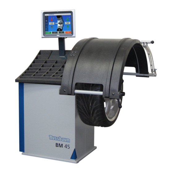
Summary of Contents for Nussbaum ATT BM Series
- Page 1 Quick Installation guide BM Wheel Balancers – new generation from Oct 2010 Status: 10. December 2013 Page 1 of 15...
- Page 2 Page 2 of 15...
-
Page 3: Table Of Contents
Content: General ............................4 Assembling the machine ......................4 Mounting the wheel hood......................5 Mounting the weight tray and the LE Display ................6 Mounting the Touch PC ......................7 Putting the machine into operation .................... 8 Electrical schematic layout ....................... 12 Dimensions .......................... -
Page 4: General
General While selecting the location for the balancer always consider the regulations and instructions of the Accident Prevention & Insurance Assocation as well as the requirements of the national working regulations. The wheel balancer can be located on each flat ground. A fastening of the machine is not compulsory. -
Page 5: Mounting The Wheel Hood
Mounting the wheel hood The wheel hood is shipped completely assembled including the shaft and wheel hood switch. It is mounted with 4 screws to the cabinet of the wheel balancer. The screws are packed in the bag together with the instruction manual. View from top View from inside of cabinet The connecting cable of the wheel hood switch has to be routed through the bore holes in the... -
Page 6: Mounting The Weight Tray And The Le Display
Mounting the weight tray and the LE Display The weight tray is fixed to the cabinet with 4 pieces of duck tape that is already present on the lower side of the weight tray as well as on the cabinet. Guide the cables for the LE Display through the hole in the weight tray and mount the weight tray to the cabinet The plugs on the cables and the connectors on the display board are marked with numbers which... -
Page 7: Mounting The Touch Pc
Mounting the Touch PC The basic balancing board where the connectors for the wheel hood switch and for the outside arm (if present) have to be connected is located inside the cabinet Guide the serial cable and the power supply cable through the monitor boom and mount the weight tray to the cabinet Connect the 2 cables as shown in the picture below Fix the Touch PC with the screw to the top of the monitor boom... -
Page 8: Putting The Machine Into Operation
Putting the machine into operation In order to set the machine into operation several general steps are required. The information on the service functions can also be found in the instruction manual DIGITAL WHEEL BALANCERS Via the function key you get into the menu for service functions to select the basic settings or change them according to the user’s requirements. - Page 9 There are 3 measuring runs performed during the calibration procedure, the wheel guard (if present) can be left open: Measuring run Run without calibration weight ® Machines with manual QuickSpan clamping of the wheel Measuring run Run with calibration weight on the left side of the mid centering device ®...
- Page 10 Zero run The Zero run is provided to electrically compensate the unbalance of the adaptor or clamping means. Whenever the clamping means has been dismounted and replaced a compensation of the residual unbalance in the adapter and clamping means should be carried out. Routine: MACHINES with manual clamping of the wheel Remove the cones and clamp from the adaptor.
- Page 11 WHEEL BALANCERS WITH TOUCH PC The settings described above for the digital wheel balancers are easily done by touch operation Calibration and zero run Button for machine calibration Button gauge calibration Page 11 of 15...
-
Page 12: Electrical Schematic Layout
Electrical schematic layout Basic Board Page 12 of 15... - Page 13 Motor control board Page 13 of 15...
-
Page 14: Dimensions
Dimensions Page 14 of 15... -
Page 15: Technical Data
Technical data Page 15 of 15...


Need help?
Do you have a question about the ATT BM Series and is the answer not in the manual?
Questions and answers