Advertisement
Quick Links
Electronic Service
Manuals
This electronic document is provided as a service to our customers.
We do not create the contents of the information contained in this docu-
ment. Should you have detailed questions pertaining to the information
contained in this document, you may contact Michco, or the manufac-
turer which provided the original information in this electronic deliver-
able. Michco's only part in this electronic deliverable was the electronic
assembly process. By providing this manual on line we are not guaran-
teeing parts availability.
You may contact Michco through the following methods:
Phone (517) 484-9312 or (800) 331-3339
2011 N. High St. -- Lansing, Michigan -- 48906
Fax: (517) 484-9836
Email: CustServe@Michco.com
Web site: www.Michco.Com
Parts Web site: www.FloorMachineParts.Com
Order Parts on Line at:
www.FloorMachineParts.Com
Directly to Parts & Service:
By Email:
Shop@Michco.com
By Fax: (517) 702-2041
By Voice: Use numbers above.
Serving the Cleaning Industry Since 1922
Notice: All copyrighted material remains property of original owners, all trademarks are property of respective owners.
Manuals are subject to Manufacturer's reproduction limitations. Originals or reproductions were provided by manufacturers
through a request. We make no warranty as to the correctness of information provided in this document and you assume
all risk. By placing these manuals on line we are not declaring our corporation to be an manufacturer authorized dealer or
provider, please check our web site for authorized manufacturers we represent.
Advertisement

Subscribe to Our Youtube Channel
Related Manuals for Clarke MA50 15B


Summary of Contents for Clarke MA50 15B
- Page 1 Electronic Service Manuals This electronic document is provided as a service to our customers. We do not create the contents of the information contained in this docu- ment. Should you have detailed questions pertaining to the information contained in this document, you may contact Michco, or the manufac- turer which provided the original information in this electronic deliver- able.
- Page 2 Clarke MA50 15B™ Service Manual Model Numbers: Clarke MA50 15B English 03/2016 - Form No. 56043172...
- Page 3 Service Manual – MA50 15B Table of Contents Contents Service Manual . . . . . . . . . . . . . . . . . . . . . . . . . . . . . . . . . . . . . . . . 1 General Information Machine Description .
- Page 4 Service Manual – MA50 15B Table of Contents Check ball-float operation . . . . . . . . . . . . . . . . . . . . . . . . . . . . . . . . 48 Troubleshooting .
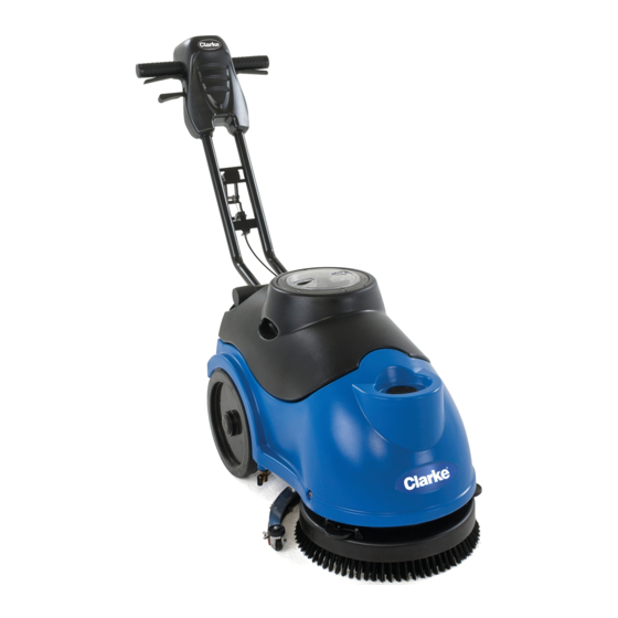
- Page 5 General Information Machine Description The CLARKE MA50 15B is a battery powered walk-behind automatic floor scrubber. It is intended for use in small to medium size commercial facilities such as retail stores. The CLARKE MA50 15B is equipped with a rotating brush to provide a 15 inch cleaning path.
- Page 6 The Clarke MA50 15B should not be lifted by any other means (i.e. dolly, forklift). Machine Transportation The Clarke MA50 15B should only be rolled on smooth floors. Do not roll the machine down stairs or curbs. Warning: Damage to the machine will occur if it is rolled down stairs or curbs ! General Safety Instructions Warning! Be sure to follow these safety precautions to avoid situations that could cause severe personal injury.
- Page 7 Service Manual – MA50 15B General Information Nameplate The nameplate contains important identification information which will be needed when ordering parts: Model number, Description, and Serial number. Machine Specifications Specification Metric Cleaning Path 15 Inches 380 Cm Solution Tank 3.5 Gallons 13.5 Liters...
- Page 8 Service Manual – MA50 15B General Information Component Locations ON/OFF Brush Vacuum Solution switch switch switch switch Recovery Tank Recovery Tank Solution Tank Solution Fill Hole Brush Deck...
- Page 9 Service Manual – MA50 15B General Information Solution Control Squeegee Brush Valve Assembly Solution Tank Drain Recovery Tank Drain cap...
- Page 10 Service Manual – MA50 15B General Information Operating Triggers Handle Adjust Lever Squeegee Lift Handle Squeegee Lift Cable...
- Page 11 Service Manual – MA50 15B General Information Preventative Maintenance DAILY WEEKLY MONTHLYMonthly Recharge Batteries Remove and clean Pad driver/ Brush Drain and rinse recovery tank. Check for solid debris Remove squeegee assembly, and wipe it down with a damp cloth...
- Page 12 Options and Accessories Options and Accessories Pad Driver The Clarke MA50 15B comes standard with a medium duty brush. An optional pad driver can be ordered through your Nilfisk dealer. Squeegee Blades The Clarke MA50 15B comes standard with neoprene rubber squeegee blades. Optional polyurethane blades can be ordered through your Nilfisk dealer .
- Page 13 Control System Functional Description The CLARKE MA50 15B has (1) Control PCB for the vacuum and brush circuits, and for the on-board charger interlock system. .The Control PCB gets input from the batteries, the on-board charger, and the switch PCB.
- Page 14 Service Manual – MA50 15B Control System Triggers Triggers Trigger switch Viewed inside control housing...
- Page 15 Service Manual – MA50 15B Control System Solution Control Valve Solution Solenoid...
- Page 16 Service Manual – MA50 15B Control System On-Board Charger Plug On-Board Charger Indicator lights Circuit Breakers Shown with Handle removed from machine, and cover removed from Circuit box On-Board Control PCB Charger...
- Page 17 Service Manual – MA50 15B Control System Maintenance and Adjustment No maintenance or adjustment is required for the control system...
- Page 18 Service Manual – MA50 15B Electrical System Electrical System Functional Description The electrical system consists of a switch panel, and a control PCB to operate the vacuum and brush motors and solution solenoid. There are also (2) circuit breakers which are used to protect the vacuum and brush motor from excessive current.
- Page 19 Service Manual – MA50 15B Electrical System Component Locations • Batteries • Battery Connector • Switch panel • Circuit Breakers • Charger plug and LED’s • Charger • Control PCB (2) 12 volt batteries wired in series Battery Connector Switch Panel...
- Page 20 Service Manual – MA50 15B Electrical System On-Board Charger Plug On-Board Charger LED Indicator lights Circuit Breakers On-Board Charger Control PCB...
- Page 21 Service Manual – MA50 15B Electrical System Wiring Harness Diagram...
- Page 22 Service Manual – MA50 15B Electrical System Battery Connections • The batteries should be connected in series as shown in the picture below. • Battery terminals and cables should be cleaned and checked periodically. • Apply a coating or protective spray on the cable connections to prevent corrosion.
- Page 23 Service Manual – MA50 15B Electrical System Battery Charging Notes • If you run the machine to the every time, you are damaging the batteries. RED LED • If you do not charge the batteries soon after the YELLOW LED comes on, the batteries continue to dis-charge, and you will damage the batteries.
- Page 24 Service Manual – MA50 15B Electrical System Lift and tilt the handle away from the machine Remove the (2) Phillips screws that hold the charger in...
- Page 25 Service Manual – MA50 15B Electrical System Disconnect the power and interlock wires 10. Remove the defective charger, and install a new one. Ensure the plug socket and the charger indiscator LED lights align with the holes in the metal cover of the machine 11.
- Page 26 Service Manual – MA50 15B Electrical System Remove the (4) Phillips screws that hold the PCB to the metal case. NOTE: There are nylon washers on the top and bottom of the PCB. Do not lose these washers When re-installing the control PCB, use a dab of grease to hold the nylon washers in place on the mounting studs.
- Page 27 Service Manual – MA50 15B Electrical System Basic Troubleshooting Problem Cause Correction • Power switch not in the ON • Turn on the machine power position switch • Batteries not connected • Connect battery connector • No Power • Batteries completely dis- •...
- Page 28 Service Manual – MA50 15B Electrical System Measurement Point Conditions Volts DC Reading • Power switch ON 24 volts DC Across the Vacuum motor spade • Vacuum switch ON terminals on the Control PCB • Any condition above not met 0 volts DC •...
- Page 29 Service Manual – MA50 15B Electrical System Measurement Point Conditions Volts DC Reading DVM Black (GND) probe on B- .3 volts DC • Charger plugged in to 110 volts AC DVM Red probe on Red connector • Charger NOT plugged in to 110 volts AC...
- Page 30 Functional Description The Clarke MA50 15B handle system is a major component of the machine. The handle system contains all of the electronics to control and operate the machine, as well as, the on-board battery charger. The handle also has a lever/gear mechanism to allow a wide variety of handle positions.
- Page 31 Service Manual – MA50 15B Handle System Switch panel (PCB behind label) Switch PCB Switch label Operating Triggers Handle Adjust Lever Front Handle Cover...
- Page 32 Service Manual – MA50 15B Handle System Squeegee Lift Lever Squeegee Cable Circuit Box Handle Pivot Point Circuit Breakers...
- Page 33 Service Manual – MA50 15B Handle System The circuit box cover was removed to show On-board the location of these Control PCB Battery parts Charger Communication cable At switch At control...
- Page 34 Service Manual – MA50 15B Handle System Removal and Replacement Switch PCB NOTE: To remove the switch PCB, you must remove the switch label. Doing so will ruin the label. Make sure you also order a new switch label when you order a new switch PCB.
- Page 35 Service Manual – MA50 15B Handle System Gently lower the rear switch cover 10. Disconnect the wire connectors from the switch PCB 11. The rear cover assembly is now free 12. Remove the switch label to access the (4) screws that attach the switch PCB to the housing. Remove the (4)
- Page 36 Service Manual – MA50 15B Handle System 13. Replace the switch label 14. Re-assemble the rear handle cover to the handle bar. Ensure the pins that are used to hold the triggers and handle adjust lever are all in place, and that no wires are pinched 15.
- Page 37 Service Manual – MA50 15B Handle System Gently lower the rear switch cover 10. Disconnect the wire connectors from the switch PCB 11. The rear cover assembly is now free 12. Remove the (2) screws that attach the trigger switch to the handle cover 13.
- Page 38 Service Manual – MA50 15B Handle System 14. Re-install the triggers onto the trigger pins. Make sure the (2) triggers “mate” in the center where they push against the switch button Triggers out of machine Triggers in machine 15. Re-assemble the front cover assembly back onto the handle bar. Make sure all of the pins for the triggers...
- Page 39 Service Manual – MA50 15B Handle System Remove the rear handle cover NOTE: The trigger handle pins can come off with the rear handle cover. Remove the (4) screws that attach the front handle cover to the metal handle Rear Cover...
- Page 40 Service Manual – MA50 15B Handle System 11. Remove the (2) Phillips screws that secure the cover plate Phillips Screws (x 2) Allen bolts (x 6) 12. Lift and tilt the handle away from the machine...
- Page 41 Service Manual – MA50 15B Handle System 13. Remove the (2) Phillips screws that hold the charger in 14. Disconnect the power and interlock wires 15. Remove the charger from the circuit box 16. Remove the (4) Allen head screws that hold the left guide block to the handle. Loosen the (4) on the right...
- Page 42 Service Manual – MA50 15B Handle System 17. You can now remove the guide block, and access the gear/spring assembly 18. Remove the entire cable with gears 19. Replace the defective parts with new, and apply a small amount of grease to the surfaces that rub together...
- Page 43 Service Manual – MA50 15B Handle System 20. Feed the cable end up through the handle tube. This takes a bit of patience, and is easier if you remove the handle from the right guide black, and reach in to help the cable go up the right tube of the handle 21.
- Page 44 Service Manual – MA50 15B Handle System 26. You can make small adjustments to the cable by removing the rubber plug on the end of the pivot point.
- Page 45 Recovery System Functional Description The recovery system on the MA50 15B is made up of a 2-stage vacuum motor, various pipes and hoses, and a ball-float assembly. The “working air” from the vacuum motor passes through the recovery tank standpipe, the ball-float assembly, then down to the squeegee.
- Page 46 Service Manual – MA50 15B Recovery System • Vacuum Seals Recovery Tank Recovery Tank Recovery Tank Latch Vacuum Motor (Shown with motor plate out of machine)
- Page 47 Service Manual – MA50 15B Recovery System Vacuum Switch Vacuum Motor circuit breaker Ball Float Assembly Standpipe...
- Page 48 Service Manual – MA50 15B Recovery System Vacuum Hose Pick Up Tube Adapter Vacuum seals x (2)
- Page 49 Service Manual – MA50 15B Recovery System Maintenance and Adjustment Check ball-float operation • Open the recovery tank cover • Remove the ball-float from the stand-pipe adapter (it just slips onto the adapter fitting) • The ball should move freely inside it’s cage all the way to the top, and all the way to the bottom •...
- Page 50 Service Manual – MA50 15B Recovery System Poor pick-up at squeegee Good water pick up performance depends on the proper amount of air flowing through the squeegee assembly. Air entering the vacuum system before the squeegee will reduce it’s ability to pick up water. Anything that restricts the movement of air through the system will also reduce it’s ability to pick up water.
- Page 51 Service Manual – MA50 15B Recovery System Remove the plastic solution feed elbow from the clip and move aside 10. Remove one of the screws and loosen the other to move the plastic retaining strips out of the way of the motor wires, and squeegee lift cable.
- Page 52 Service Manual – MA50 15B Recovery System • Repeat for the left side bolts. NOTE: The shorter Allen bolt toward the rear of the machine is used as a “stop” • You can now carefully move the entire brush head out of the way to gain access to the squeegee cable mounting brackets 12.
- Page 53 Service Manual – MA50 15B Recovery System 13. Remove the (2) plastic tie down brackets that hold the vacuum motor to the metal deck plate 14. Remove the sound reducing foam from the defective vacuum motor 15. Remove the defective vacuum motor from the machine...
- Page 54 Service Manual – MA50 15B Recovery System Vacuum Seals Remove and drain the recovery tank Remove the (3) screws that hold in the vacuum seals Screws Lift up the plastic strap, and you can now slip the vacuum seals off from the hose cuffs, and out of the plastic strip Slip the old seals out of the plastic, and slip the replacement seals in.
- Page 55 Service Manual – MA50 15B Recovery System Re-assemble the seals and re-install the plastic retaining strip Vacuum Motor Switch The vacuum motor switch cannot be replaced separately. The entire switch PCB must be replaced. For detailed instructions on replacing the switch PCB, see the HANDLE SYSTEM section of this manual.
- Page 56 Functional Description The Clarke MA50 15B uses a single 1/3 horse power motor to turn a belt driven pulley at 150 rpm. The MA50 15B has a “pivoting head” design, so the brush pressure is limited to the weight of the front of the machine. The only variation in brush pressure is the weight of the water in the tanks.
- Page 57 Service Manual – MA50 15B Scrub System Switch PCB (Behind Label) Power Switch Brush Switch Operating Triggers...
- Page 58 Service Manual – MA50 15B Scrub System Brush Circuit Breaker This view is shown with the handle and circuit box cover removed Control PCB...
- Page 59 Service Manual – MA50 15B Scrub System This view shown with motor plate removed from machine Brush motor Driven Pulley Drive Belt...
- Page 60 Service Manual – MA50 15B Scrub System Belt Tension Pulley The Belt Tension Bracket and Spring are located on the opposite side of the driven puley Belt Tension Spring Belt Tension Bracket...
- Page 61 Service Manual – MA50 15B Scrub System Troubleshooting Problem Causes Solution • The machine is being used for • The motor is overheating work it was not designed to handle • Check the driven pulley for strings • The driven pulley cannot spin...
- Page 62 Service Manual – MA50 15B Scrub System 10. The belt routing is shown in this picture. Note that the “ribbed” side of the belt fits into the grooves on the brush motor shaft, and the “smooth” side of the belt rides on the Idler and driven pulleys.
- Page 63 Service Manual – MA50 15B Scrub System Remove the plastic solution feed elbow from the clip and move aside Remove one of the screws and loosen the other to move the plastic retaining strips out of the way of the motor wires, and squeegee lift cable.
- Page 64 Service Manual – MA50 15B Scrub System • Repeat for the left side bolts. NOTE: The shorter Allen bolt toward the rear of the machine is used as a “stop” • You can now carefully move the entire brush head out of the way to gain access to the brush motor.
- Page 65 Service Manual – MA50 15B Scrub System 12. Remove the drive belt 13. Remove the large nut that holds the driven pulley 14. Remove the pulley to gain access to the brush motor mounting screws 15. Remove the (4) brush motor mounting screws. You will have to swing the squeegee bracket to get all the...
- Page 66 Service Manual – MA50 15B Scrub System 16. Cut the wire ties, and disconnect the brush motor connector 17. Install the new brush motor in the reverse order Shop Measurements • Amp draw of brush motor (free spin) - 2.8 amps •...
- Page 67 Service Manual – MA50 15B Solution System Solution System Functional Description The solution system is gravity feed, meaning there is no pump for the solution. The solution system is fed through a manual petcock (for adjusting solution flow) to a tube which connects to the solution valve.
- Page 68 Service Manual – MA50 15B Solution System Component Locations • Solution Tank • Solution Shut-off/Adjustment Valve • Solution Valve (solenoid) • Solution Switch Solution Tank Solution Adjust/Shut-off Valve...
- Page 69 Service Manual – MA50 15B Solution System Solution Valve (Solenoid) Solution Switch...
- Page 70 Turn the power switch to ON, turn the Brush switch ON, turn the Solution switch ON. A full stream of water should flow out of the plastic elbow clipped to the brush deck There is no solution filter on the MA50 15B, so if there is a restriction, it will be in the valve, solenoid, or tubes Troubleshooting...
- Page 71 Service Manual – MA50 15B Solution System Removal and Installation Solution Solenoid Note: Replacing the solution solenoid is difficult, and should only be done when you are certain it is a problem. Remove all water from the solution and recovery tanks Remove the Recovery tank Remove the batteries as a “pack”, and set out of the way...
- Page 72 Service Manual – MA50 15B Solution System Now the solution solenoid is only attached to the machine by the wires. To get to the connector on the control PCB, you will need to remove the circuit box cover 10. Flip the machine right side up, and remove the (6) Allen bolts that attach the handle to the machine, and (2) Phillips screws, that hold the circuit box cover on.
- Page 73 Service Manual – MA50 15B Solution System 13. “Snake” the cable and connector from the replacement solution solenoid through the machine, and install the connector onto the control PCB. The connector is “keyed” so pay attention 14. Remove the (2) Allen bolts that were holding the handle in place, and re-install the (2) cover screws 15.
- Page 74 Service Manual – MA50 15B Solution System Control PCB Remove the recovery tank Disconnect batteries Remove batteries as a “pack” Remove (5) of the (6) Allen bolts w/acorn nuts. NOTE: The (2) longer Allen bolts go through the support brackets...
- Page 75 Service Manual – MA50 15B Solution System Lift and tilt the handle away from the machine Disconnect all of the wires and connectors from the PCB. The terminals for the 12 gauge wires from the batteries are screwed to the PCB with short Phillips screws...
- Page 76 Service Manual – MA50 15B Solution System 10. Remove the (4) Phillips screws that hold the PCB to the metal case. NOTE: There are nylon washers on the top and bottom of the PCB. Do not lose these washers 11. When re-installing the control PCB, use a dab of grease to hold the nylon washers in place on the mounting studs.
- Page 77 Squeegee System Functional Description The CLARKE MA50 15B uses a parabolic style squeegee assembly attached to a swiveling squeegee mount bracket with (2) thumb screws. The squeegee is raised and lowered manually using the squeegee lift lever, and the squeegee lift cable. Down pressure on the squeegee is obtained by using a spring on the the squeegee mount bracket.
- Page 78 Service Manual – MA50 15B Squeegee System Squeegee Assembly Squeegee Thumb Screws...
- Page 79 Service Manual – MA50 15B Squeegee System Squeegee Lift Handle Squeegee Lift Cable...
- Page 80 Service Manual – MA50 15B Squeegee System Maintenance and Adjustment Adjusting the Squeegee down pressure • The squeegee down pressure can be adjusted so that there is a gentle deflection across the entire blade while traveling in the forward direction. This deflection places the edge of the squeegee blade in the proper position for “wiping”...
- Page 81 Service Manual – MA50 15B Squeegee System Removal and Installation Squeegee Lift Cable Drain both the Solution and Recovery tanks Remove the recovery tank Remove the batteries as a “pack” Use the Squeegee lift lever on the handle to lower the squeegee assembly...
- Page 82 Service Manual – MA50 15B Squeegee System Remove the plastic solution feed elbow from the clip and move aside 10. Remove one of the screws and loosen the other to move the plastic retaining strips out of the way of the motor wires, and squeegee lift cable.
- Page 83 Service Manual – MA50 15B Squeegee System • Repeat for the left side bolts. NOTE: The shorter Allen bolt toward the rear of the machine is used as a “stop” • You can now carefully move the entire brush head out of the way to gain access to the squeegee cable mounting brackets 12.
- Page 84 Service Manual – MA50 15B Squeegee System 13. Remove the (2) plastic clamps that hold the squeegee to the rear of the machine...
- Page 85 Service Manual – MA50 15B Squeegee System 14. Remove one of the brass “rollers” on the handle, and disassemble the pin at the squeegee lift handle 15. Snake the cable out of the machine 16. Replace in reverse order Squeegee Blades...
- Page 86 Service Manual – MA50 15B Squeegee System Now remove the plastic backing strips. NOTE: The inside backing strip is shorter than the outside strip You can now remove the squeegee blades. NOTE: Both squeegee can be flipped, and used again. The...
- Page 87 Service Manual – MA50 15B Squeegee System Troubleshooting Problem Cause Correction Vacuum leak(s) due to; • Leaky Vacuum hose • Check the vacuum hose, and tighten/replace as necessary • Damaged pick-up adapter tube • Replace pick up adapter tube • Recovery tank drain plug not •...
Need help?
Do you have a question about the MA50 15B and is the answer not in the manual?
Questions and answers