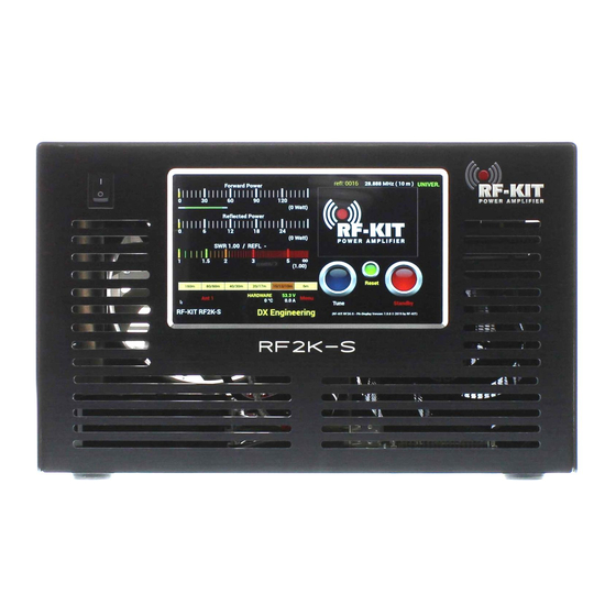
RF-KIT RF2K-S Assembly And Adjustment Instructions
Linear amplifier
Hide thumbs
Also See for RF2K-S:
- Operating and installing instructions (28 pages) ,
- User manual (36 pages)
Summary of Contents for RF-KIT RF2K-S
- Page 1 Assembly and adjustment instructions for linear amplifier RF2K-S .-. ..-. -..- -.- .. - .--. --- .-- . .-. .- -- .--. .-..-..-. Bedienungs- und Installationsanleitung RF-KIT Linearverstärker RF2K-S...
-
Page 2: Table Of Contents
Test of the frequency measurement and the lowpass filter circuit 1. Explanation of symbols, Environment protection Congratulations on your purchase of a RF-KIT linear amplifier! Adjustment power display Explanation of symbols RF-KIT devices offer innovative and reliable technology, functionality and... -
Page 3: Explanation Of Symbols, Environment Protection
If you plan to dispose of the packing by yourself, please locate the nearest recycling center. Important information without danger to people or proper- ty is marked by the adjacent symbol. These informations are boanded by lines above and below the text. Assembly and adjustment instructions RF-KIT Power Amplifier RF2K-S... -
Page 4: Step 2: Removing The Housing Cover
2x USB-cable (USB-Mini to USB; approx. 0.5 m) 1x HDMI-cable (HDMI-Micro to HDMI; approx. 0.5 m) These 3 cables are included in the delivery, in addition to a power plug and a piece of coaxial cable with SMA plug. Assembly and adjustment instructions RF-KIT Power Amplifier RF2K-S... -
Page 5: Step 5: Installing Raspberry Pi® 4 Model B
The free software must therefore be installed after downloading, which requires administrative rights on the computer. Installing a version of the operating system other than that intended for your country will void the warranty. (continued on next page) Assembly and adjustment instructions RF-KIT Power Amplifier RF2K-S... - Page 6 A - Micro HMDI / B - Micro HMDI / C - Power supply / D, E - 2x USB / The socket “2 - Mini USB“ of the Controller board will not be used and F - LAN therefore remains free. Assembly and adjustment instructions RF-KIT Power Amplifier RF2K-S...
-
Page 7: Raspberry Pi® 4 Model B
► Connect “K - Power supply“ of the Touch screen (2) to “3 - USB“ on the Controller board. Socket “A - Micro HMDI“ on the Raspberry Pi® 4 Model B will not be used and therefore remains free. Assembly and adjustment instructions RF-KIT Power Amplifier RF2K-S... -
Page 8: Step 9: Preparatory Work For Alignment
Use a cable with the shortest possible length and the largest possible cross-section. ► Connect the unit to the mains using the power cable via the Power jack (9) on the rear panel. Assembly and adjustment instructions RF-KIT Power Amplifier RF2K-S... -
Page 9: Adjustment
(14 MHz). On/Off Fig. below: Position of the potentiometers relevant for the adjustment on Touch screen the Controller board. ANT 1 Power jack Rear panel: 11 Ground connector 17 Exciter input Assembly and adjustment instructions RF-KIT Power Amplifier RF2K-S... -
Page 10: Adjustment Power Display
► Set R24 on the Controller board so that on the Touch screen (2) ► Release PTT, stop transmitting. (main screen) the transmit power supplied by the TRX is displayed with the correct value as forward power. R525 R526 ► Release PTT, stop transmitting. Assembly and adjustment instructions RF-KIT Power Amplifier RF2K-S... -
Page 11: Adjustment Reflected Power Display
The bargraph of the reflected power on the main screen will deflect full, but the digital power display will still show the value to be adjusted cor- rectly. ► Release PTT, stop transmitting. Assembly and adjustment instructions RF-KIT Power Amplifier RF2K-S... -
Page 12: Adjustment Display Current Consumption
3.6 A is displayed on the Touch screen (2). ► Release PTT, stop transmitting. ► Plug the SMA plug back into the input SMA socket PA module. Delivery status: “BIAS OFF“ Operating status: “BIAS ON“ Fig. right: PA module Assembly and adjustment instructions RF-KIT Power Amplifier RF2K-S... -
Page 13: Adjustment Forward Power Display
Brief actuation changes the value in the indication area Forward by 0.1 W. Longer actuation changes the value continuously. ► Press the switching area Save to store the settings. ► Repeat this procedure for each bandpass range to be adjusted. Assembly and adjustment instructions RF-KIT Power Amplifier RF2K-S... -
Page 14: Optional Power Fine Tuning Via The Menu
► Adjust the output power by tapping switching areas > (increase value) respectively < (decrease value). Brief actuation changes Calibration Value by 1 digit. Longer actuation changes the value continuously (factory setting: 100.0). Assembly and adjustment instructions RF-KIT Power Amplifier RF2K-S... - Page 15 Assembly and adjustment instructions RF-KIT Power Amplifier RF2K-S...
- Page 16 Reinhard Förtsch · DH3NAB Heuleithe 14 · 91322 Gräfenberg mail@rf-kit.de · www.rf-kit.de .-. ..-. -..- -.- .. - .--. --- .-- . .-. .- -- .--. .-..-..-. Bedienungs- und Installationsanleitung RF-KIT Linearverstärker RF2K-S...


Need help?
Do you have a question about the RF2K-S and is the answer not in the manual?
Questions and answers