
Subscribe to Our Youtube Channel
Related Manuals for ITW SIMCO ION Pinner-LP

Summary of Contents for ITW SIMCO ION Pinner-LP
- Page 1 Chargemaster Pinner-LP Arc Resistant Charging Bars INSTALLATION AND OPERATING INSTRUCTIONS Chargemaster Pinner-LP 52 01 2 29 Re v A...
- Page 2 (This page intentionally left blank.) Chargemaster Pinner-LP 52 01 2 29 Re v A...
-
Page 3: Table Of Contents
TABLE OF CONTENTS 1. SAFETY WARNINGS ................1 2. DESCRIPTION ................... 2 3. FEATURES ..................3 4. SPECIFICATIONS ................4 5. INSTALLATION .................. 5 Unpacking ..........................5 Determining Pinner-LP Bar Location ..................5 Mounting Charging Bars ......................7 Installing High Voltage Cables .....................9 6. - Page 4 (This page intentionally left blank.) Chargemaster Pinner-LP 52 01 2 29 Re v A...
-
Page 5: Safety Warnings
1. SAFETY WARNINGS NOTE: Statements identified with a NOTE indicate precautions necessary to avoid potential equipment failure. CAUTION! Statements identified with a CAUTION indicate minor or moderate injury is possible. WARNING! Statements identified with a WARNING indicate serious injury is possible. NOTE: –... -
Page 6: Description
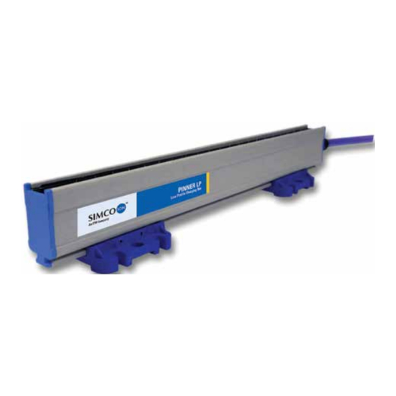
2. DESCRIPTION Simco-Ion’s Arc Resistant Charging Bars are part of the Chargemaster Electrostatic Generating System. These bars are energized with Simco-Ion Chargemaster VCM30, CM20, MCM30 DC power supplies that provide the necessary high voltage that is current limited for safety. This system is used to produce electrostatic adhesion for temporarily bonding or pinning materials. -
Page 7: Features
3. FEATURES • Increased voltage consistency and pinning action. • Low profile design. • Reduced EMI/RMI that can disturb sensitive electronic components. • Limited energy release that could otherwise degrade some plastics and other materials causing additional damage and failures. •... -
Page 8: Specifications
4. SPECIFICATIONS Input Voltage: ±30 kVDC max Output Current: Continuous Use: 0.75 mA/ft max Intermittent Use: 1.50 mA/ft max Operating Environment: 32°F (0°C) to 200°F (90°C); 70% RH max, no dewing permissible Operating Distance: 1/2” to 3” (application & voltage dependent) Weight: 1.4 lb per foot Dimensions:... -
Page 9: Installation
5. INSTALLATION Unpacking Carefully remove equipment from the carton and inspect the contents. NOTE: If any damage has occurred during shipment, notify the local carrier at once. A report should also be forwarded to Simco-Ion, 2257 North Penn Road, Hatfield PA 19440. See Section 9 (Warranty) for Return Shipment information. Determining Pinner-LP Bar Location Although Simco-Ion’s Pinner-LP bars prevent hard arcs from occurring, the bars do exhibit a soft arcing that can be both useful in setting up the application and useful in... - Page 10 Option 1: Charging Bar with a Grounded Surface In Figure 1, the charging bar faces an empty core in a roll-to- roll changeover application. The empty core is mounted on a grounded metal shaft and a plastic film travels between the charging bar and the empty core.
-
Page 11: Mounting Charging Bars
Option 3: Two Charging Bars In Figure 4, one charging bar faces another of opposite polarity in an application where decorative sheets are pinned to both sides of heavy particle board prior to laminating. As the materials move between the charging bars, the opposite polarity ions created by each bar are driven toward each other by an electric field formed between them. - Page 12 Determine the best location for the Pinner-LP Bar using the above applications for guidance. The Pinner-LP bar includes blue plastic mounting brackets, perforated metal strips and assorted hardware. Slide the mounting brackets onto the “T” channel on the back of the bar. The perforated strip may be installed on the mounting bracket at right angle to the bar or parallel to the bar.
-
Page 13: Installing High Voltage Cables
Installing High Voltage Cables CAUTION! Electrical Shock Hazard Turn off power supply and lock out before connecting high voltage cable or servicing. Route the high voltage cables attached to each charging bar along the machine frame or wall to the power supply. Cable supports are used to guide the cables back to the power supply. -
Page 14: Operation
6. OPERATION CAUTION! Electrical Shock Hazard Do not touch Charging Bar during operation. WARNING! Fire Hazard Do not operate equipment in close proximity to any flammable solvents or flammable materials. Before energizing any power supply: • Ensure that all power supplies are properly grounded. •... -
Page 15: Maintenance
7. MAINTENANCE NOTE: Only qualified service personnel are to perform maintenance tasks. CAUTION! Electrical Shock Hazard De-energize all power supplies and lock out, if possible, before performing any maintenance tasks. Cleaning Emitter Pins Dust or dirt around the emitter pins will reduce the effectiveness of the Pinner-LP Bar. The bar must be cleaned periodically to prevent deposits from accumulating: De-energize all power supplies before performing any maintenance tasks. -
Page 16: Troubleshooting Low Pinning Strength
Troubleshooting Low Pinning Strength • If pinning strength is not adequate and the power supply is already at maximum output voltage, moving the bar closer to the target material can increase pinning strength. Reduce the bar-to-material distance until pinning strength is adequate. At this new distance, it may be necessary to adjust the operating voltage of the power supply. -
Page 17: Replacement Parts
8. REPLACEMENT PARTS Part Number Description 4104481 Cable Support, 7/16” diameter cable 4100286 SLCC HV Connector Kit (30 kV) 4670204 Nylon Cleaning Brush 4810276 High Voltage Cable 4800293 High Voltage Cable Sleeve 4006320 Connector Block Kit (30kV)* *Allows the bar to be removed from service without disturbing other cables running to a remotely located power supply. -
Page 18: Warranty
9. WARRANTY Simco-Ion warrants its products to be free of defects in components, workmanship, or materials for a period of one year from date of purchase. This warranty does not apply to any physical or electrical damage caused by misuse, abuse or negligence (such as any modifications made to the unit or service work done by any other than Simco-Ion authorized technicians). - Page 19 (This page intentionally left blank.) Chargemaster Pinner-LP 52 01 2 29 Re v A...
- Page 20 Simco-Ion 2257 North Penn Road Hatfield, PA 19440 (215) 822-6401 (800) 203-3419 www.simco-ion.com customerservice@simco-ion.com © 2014 Simco-Ion Printed in the U.S.A. Chargemaster Pinner-LP 52 01 2 29 Re v A...
Need help?
Do you have a question about the SIMCO ION Pinner-LP and is the answer not in the manual?
Questions and answers