Table of Contents
Advertisement
Available languages
Available languages
Quick Links
Advertisement
Table of Contents

Related Manuals for Rebel MIE-RB10B


Summary of Contents for Rebel MIE-RB10B
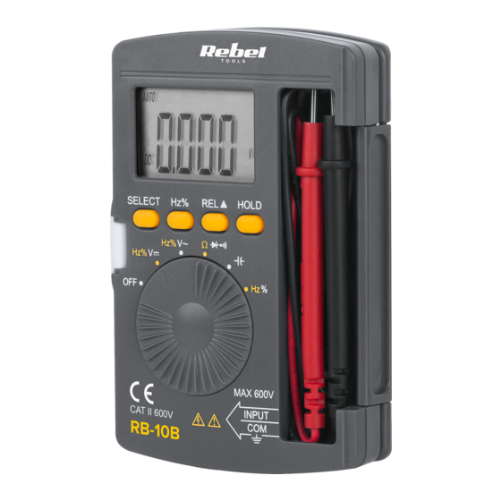
- Page 1 TOOLS POCKET MULTIMETER USER’S MANUAL model: MIE-RB10B...
- Page 3 SICHERHEITSANWEISUNGEN Um einen elektrischen Schlag, oder Verletzungen zu vermeiden, befolgen unteren Sicherheitsanweisungen: Überprüfen Sie das Gehäuse vor der Verwendung des Geräts auf mechanische Beschädigungen. Verwenden Sie das Gerät nicht, wenn das Gehäuse Risse aufweist oder Teile fehlen. 2. Überprüfen Sie vor der Verwendung des Geräts die Messleitungen auf Beschädigungen.
-
Page 4: Betrieb
Messungen verringert werden. 11. Vor dem Öffnen des Batteriegehäuses die Messleitungen vom Messkreis und vom Gerät trennen. 12. Die Batterie muss durch eine neue mit derselben Spezifikation ersetzt werden. 13. Manipulieren Sie nicht die internen Schaltkreise des Geräts. Dies kann zu einer Verringerung der Genauigkeit oder zu einer Beschädigung des Geräts führen. - Page 5 3. Das Ergebnis erscheint am Display. Bei der Gleichstrommessung (DC), wird die Polarität der roten Messleitung angezeigt. 4. Um Modus Frequenz oder Arbeitszyklusmessung zu ändern, drücken Sie die Taste Hz%. Hinweis: • Seien Sie besonders vorsichtig, wenn Sie hohe Spannungen messen. •...
- Page 6 Durchgangsprüfung Setzen Sie den Drehschalter auf Position 2. Drücken Sie zweimal die Taste SELECT und das Symbol wird angezeigt. 3. Verbinden Sie die Messleitungen mit dem Messkreis. 4. Wenn der Widerstand unter 30 Ω ist, ertönt der Summer. Diodenmessung Setzen Sie den Drehschalter auf Position 2.
-
Page 7: Reinigung Und Wartung
Frequenz- und Arbeitszyklusmessung • Setzen Sie den Drehschalter auf Position Hz%. • Drücken Sie die Taste Hz% zum Umschalten zwischen Frequenz- und Arbeitszyklusmessung. • Verbinden Sie die Messleitungen mit dem Messkreis. Das Messergebnis erscheint am Display. Achtung: Die Eingangsspannung sollte im Bereich zwischen 200 mV und 10 V AC liegen. - Page 8 400 V 100 mV ±(0,8% + 3) 600 V ±(1% + 5) • Eingangsimpedanz: 10 MΩ • Überlastschutz: 600 V AC und DC (für 200 mV Bereich: 250 V DC/AC) • Max. Eingangsspannung: 1000 V DC Wechselspannung [AC] Bereich Auflösung Genauigkeit 400 mV 1 mV...
- Page 9 Widerstand Range Resolution Accuracy 400 Ω 0,1 Ω ±(1,2% + 8) 4 KΩ 1 Ω 40 KΩ 10 Ω ±(1,2% + 5) 400 KΩ 100 Ω 4 MΩ 1 KΩ 40 MΩ 10 KΩ ±(1,5% + 5) • Max. Spannung des offenen Messkreises: etwa 0,25 V •...
- Page 10 • Wenn der Widerstand höher als 100 Ω ist, bleibt der Summer stumm. Kapazität Bereich Auflösung Genauigkeit 40 nF 10 pF ±(5% + 10) 400 nF 100 pF 4 µF 1 nF ±(5% + 5) 40 µF 10 nF 100 µF 100 nF Frequenz (automatischer Bereich) Bereich...
- Page 11 Deutsch Korrekte Entsorgung dieses Produkts (Elektromüll) (Anzuwenden in den Ländern der Europäischen Union und anderen europäischen Ländern mit einem separaten Sammelsystem) Die Kennzeichnung auf dem Produkt bzw. auf der dazugehörigen Literatur gibt an, dass es nach seiner Lebensdauer nicht zusammen mit dam normalem Haushaltsmüll entsorgt werden darf.
-
Page 12: Safety Instructions
SAFETY INSTRUCTIONS In order to avoid electric shock or other injuries, follow the safety instructions below: Before using the device, inspect the case for any mechanical damage. If the case has cracks or is missing any part, do not use the device. 2. -
Page 13: Product Description
13. Do not tamper with devices internal circuits. This may lead to accuracy decrease or damaging the device. 14. The device is intended for indoors use only. 15. Take out the battery, if the device is not going to be used for a long time. 16. - Page 14 Note: • Take extra caution while measuring high voltages. • Frequency and duty cycle measurements are not conducted while in DC voltage mode. Resistance measurement Set the rotary switch to p o s i t i o n . A f t e r selecting the range, the default mode is resistance measurement.
- Page 15 4. If the resistance is lower than 30 Ω, the buzzer will buzz. Diode measurement Set the rotary switch to position. 2. Press the SELECT button, and the icon will appear 3. Connect the red lead to anode of the diode, and black to the cathode.
-
Page 16: Cleaning And Maintenance
range, the result may be inaccurate or be out of scale. CLEANING AND MAINTENANCE • Clean the device with soft, slightly damp cloth, without abrasive agents. • To change the battery and the fuse, unscrew four screws from the back of the device. After opening the battery cover, replace the battery (note the polarity). - Page 17 AC voltage Range Resolution Accuracy 400 mV 1 mV ±(1,2% + 8) 1 mV 40 V 10 mV ±(1% + 8) 400 V 100 mV 600 V ±(1,2% + 8) • Input impedance: 10 MΩ • Average responding calibrated in rms of a sine wave.
- Page 18 Diodes and continuity Range Description Remarks Open circuit Voltage drop will voltage: approx. be shown 1,5 V If the resistance Open circuit is lower than 30 voltage: approx. Ω, the buzzer 0,5 V will buzz • Overload protection: 250 V DC/AC •...
- Page 19 Frequency (auto range) Range Accuracy 5/50/500/5 K ±(1% + 3) 50K/500K/5 Mhz English Correct Disposal of This Product (Waste Electrical & Electronic Equipment) (Applicable in the European Union and other European countries with separate collection systems) This marking shown on the product or its literature, indicates that it should not be disposed with other household wastes at the end of its working life.
- Page 20 KWESTIE BEZPIECZEŃSTWA W celu uniknięcia porażenia elektrycznego lub innej kontuzji podczas korzystania z urządzenia, należy stosować się do poniższych zasad bezpieczeństwa: Przed rozpoczęciem korzystania z urządzenia należy sprawdzić jego obudowę pod kątem uszkodzeń mechanicznych. Jeżeli obudowa posiada pęknięcia lub braki, nie należy korzystać z urządzenia.
-
Page 21: Opis Urządzenia
10. Jeżeli na wyświetlaczu pojawia się komunikat o niskim poziomie baterii, należy wymienić baterię. W przeciwnym wypadku dokładność pomiarów może zostać zmniejszona. 11. Przed otwarciem pokrywy baterii należy odłączyć przewody testowe od mierzonego obwodu oraz od urządzenia. 12. Części zamienne (bateria i bezpiecznik) należy wymieniać... - Page 22 OBSŁUGA Pomiar napięcia Ustawić przełącznik wyboru trybu do pozycji 2. Podłączyć przewody pomiarowe do źródła pomiaru. 3. Wynik zostanie podany wyświetlaczu. Podczas pomiaru napięcia DC, zostanie podana polaryzacja czerwonego przewodu. 4. Aby dokonać pomiaru częstotliwości lub współczynnika wypełnienia, należy nacisnąć przycisk Hz%. Uwaga: •...
- Page 23 w zakresie od 0,1 do 0.9. Aby uzyskać dokładny pomiar należy zewrzeć ze sobą przewody pomiarowe i odjąć wynik od pomiaru, lub po zwarciu przewodów pomiarowych użyć funkcji REL. • Jeżeli rezystancja jest wyższa niż MΩ należy odczekać chwilę aż wynik pomiaru się...
-
Page 24: Czyszczenie I Konserwacja
Uwaga: • Przed pomiarem należy rozładować wszystkie kondensatory. • Podczas pomiaru kondensatorów większych niż 10 µF należy odczekać, aż pomiar ustabilizuje się. Pomiar częstotliwości i współczynnika wypełnienia • Ustawić przełącznik wyboru trybu do pozycji Hz%. • Nacisnąć przycisk Hz%, aby przełączać między pomiarem częstotliwości i cyklem pracy. - Page 25 SPECYFIKACJA Napięcie DC Zakres Rozdzielczość Dokładność 400 mV 0,1 mV ±(0,8% + 5) 1 mV 40 V 10 mV ±(0,8% + 3) 400 V 100 mV 600 V ±(1% + 5) • Impedancja wejściowa: 10 MΩ • Ochrona przed przeciążeniem: 600 V AC i DC (dla zakresu 200 mV: 250 V DC/AC) •...
- Page 26 • Maksymalne napięcie wejściowe: 600 V AC Rezystancja Zakres Rozdzielczość Dokładność 400 Ω 0,1 Ω ±(1,2% + 8) 4 KΩ 1 Ω 40 KΩ 10 Ω ±(1,2% + 5) 400 KΩ 100 Ω 4 MΩ 1 KΩ 40 MΩ 10 KΩ ±(1,5% + 5) •...
- Page 27 • Jeżeli rezystancja jest wyższa niż 100 Ω, głośnik nie wyda dźwięku. Pojemność Zakres Rozdzielczość Dokładność 40 nF 10 pF ±(5% + 10) 400 nF 100 pF 4 µF 1 nF ±(5% + 5) 40 µF 10 nF 100 µF 100 nF Częstotliwość...
- Page 28 Poland Prawidłowe usuwanie produktu (zużyty sprzęt elektryczny i elektroniczny) Oznaczenie umieszczone na produkcie lub w odnoszących się do niego tekstach wskazuje, że po upływie okresu użytkowania nie należy usuwać z innymi odpadami pochodzącymi z gospodarstw domowych. Aby uniknąć szkodliwego wpływu na środowisko naturalne i zdrowie ludzi wskutek niekontrolowanego usuwania odpadów, prosimy o oddzielenie produktu od innego typu odpadów oraz odpowiedzialny recykling w celu promowania ponownego użycia zasobów materialnych jako stałej...
-
Page 29: Instrucțiuni Privind Siguranța
INSTRUCȚIUNI PRIVIND SIGURANȚA Pentru a evita un posibil șoc electric sau vătămare corporală și pentru a evita posibilele deteriorări ale multimetrului și ale echipamentului testat, respectați următoarele reguli: Inspectați sondele de test pentru a verifica dacă există izolație deteriorată sau metal expus. Nu utilizați aparatul dacă... -
Page 30: Descrierea Produsului
măsurat și de la dispozitiv. 11. Bateria trebuie înlocuită cu una nouă care are aceleași specificații. 12. Nu modificați circuitele interne ale dispozitivelor. Aceasta poate duce la scăderea preciziei sau la deteriorarea dispozitivului. 13. Multimetrul este proiectat pentru a se utiliza doar în spațiu inchis. - Page 31 sau a factorului de umplere, apăsați butonul Hz%. Note: • Aveți grijă în timp ce măsurați tensiuni mari. • Măsurarea frecvenței și a factorului de umplere nu se efectuează în modul de tensiune DC. Măsurare rezistență Setați comutatorul rotativ în poziția .
- Page 32 pictograma 3. Conectați cablurile de testare la circuitul măsurat. 4. Dacă rezistența este mai mică de 30 Ω, alarma va suna. Măsurare diode Setați comutatorul rotativ în poziția 2. Apăsați butonul SELECT, va fi afișată pictograma 3. Conectați cablul roșu la anodul diodei, iar cel negru la catod.
-
Page 33: Curățare Și Întreținere
• Conectați cablurile de testare la circuitul măsurat. Rezultatul va fi afițat pe ecran. Atenție: tensiunea de intrare trebuie să fie cuprinsă între 200 mV și 10 V AC. Dacă tensiunea depășește intervalul, rezultatul poate fi inexact sau nu se poate efectua măsurătoarea. - Page 34 • Impedanță intrare: 10 MΩ • Protecție la suprasarcină: 600 V AC și DC (pentru domeniul 200 mV: 250 V DC/AC) • Tensiunea de intrare max.: 1000 V DC Tensiune AC Nivel Rezoluție Precizie 400 mV 1 mV ±(1,2% + 8) 1 mV 40 V 10 mV...
- Page 35 • Tensiunea max. a circuitului deschis: 0,25 V • Protecție la suprasarcină: 250 V DC/AC Diode și continuitate Nivel Descriere Comentarii afișată Tensiune circuit căderea deschis: aprox. tensiune. 1,5 V Dacă rezistența Tensiune circuit este mai mică de deschis: aprox. 30 Ω, va suna 0,5 V alarma.
- Page 36 Frecvență (interval automat) Nivel Precizie 5/50/500/5 K ±(1% + 3) 50K/500K/5 Mhz Romania Reciclarea corecta a acestui produs (reziduuri provenind din aparatura electrica si electronica) Marcajale de pe acest produs sau mentionate in instructiunile sale de folosire indica faptul ca produsul nu trebuie aruncat impreuna cu alte reziduuri din gospod arie atunci cand nu mai este in stare de functionare.
- Page 40 www.rebelelectro.com...
Need help?
Do you have a question about the MIE-RB10B and is the answer not in the manual?
Questions and answers