Advertisement
Quick Links
Advertisement

Subscribe to Our Youtube Channel
Related Manuals for DHK Hobby TIGER

Summary of Contents for DHK Hobby TIGER
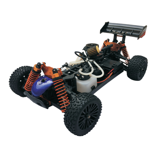
- Page 1 1/10th 4WD Nitro Buggy Model# 9131...
- Page 2 Failure to do so might shorten the lifespan of your model. You are cordially advised that DHK Hobby makes all necessary parts and accessories to support you for any problem during and after driving.
- Page 3 Receiver battery charger. Tools. Hex wrenches, and screwdrivers. 2 Channel 2.4GHz radio system TIGER comes with a full function 2 channel 2.4GHz radio transmitter and receiver. Please refer to the 2.4GHz User’s Instructions Manual for detail. Gears : Plastic gears, ball bearings Working voltage : 4.8-6.0V...
- Page 4 1.Always test the brakes and the throttle before starting your engine to avoid losing control of the model. 2.Make sure the air filter is clean and that oil is put on air filter. 3.Never run your engine without an air filter. Your engine can be seriously damaged if dirt and debris get inside it.
- Page 5 When you lean out a nitro engine, you are adjusting the air/fuel mixture so that there is more air going into the nitro engine than there is fuel. This provides a little more horsepower but can result in very high engine temperatures. If you are not careful leaning out a nitro engine, you could run it too lean.
- Page 6 Proper nitro engine break-in is critical for long-lasting performance of your RC. Every new nitro engine should undergo a break-in procedure. Breaking in a nitro engine takes anywhere from one to two hours and about 5-8 tanks of nitro fuel. If you do the nitro engine break-in properly, the up-keep on your RC vehicle is less costly than if the procedure is done hastily and incorrectly.
- Page 7 Give the engine one-quarter throttle slowly for 2 seconds. Apply the brakes. If you pull back on the throttle too fast, you may cause your engine to stall When there is a nice trail of blue smoke coming from the exhaust, it means your fuel mixture is properly set and the engine is being lubricated.
- Page 8 There are several ways to stop the engine: 1)Use a rag to cover the exhaust tip. Be careful! The exhaust is extremely hot so use a thick rag and gloves. 2)Pinch the fuel tubing to stop the flow of fuel to the carb. Be careful, this can make the motor run lean which can damage the motor.
- Page 9 Part# Description Part# Description 8381-609 Screw bushing (4 pcs) Flathead screw-coarse 8381-104 thread(KB2.6*10mm) (16 pcs) 8381- 6Z0 Assembly of steering linkage (2PCS) Crown gear-41T (large)/pinion gear-11T 8381- 6Z1 Steering linkage (2 pcs) 8381-105 (small) 8381-6Z2 Plastic rod end (8 pcs) 8381-106 Diff case set/diff case cover/diff gasket 8381-6Z3 Double way ball end (8 pcs) 8381-107 Washer -A/washer-B (8 pcs each)
- Page 10 Description Part# 9131-600 Servo saver assembly-complete 9131-801 Rear wing (black) 9131-9B1 Brake arm//brake collar-A/set screws (M3*3mm) 9131- 9B2 Collar-B/O-ring-A/revolving brace 9131-9B3 Throttle linkage/brake linkage 9131-9E1 Engile flywheel 9131-9E2 Air filter joint pipe 9131-9E3 Air filter case 9131- 9E4 Air filter sponge 9131-9T0 Fuel tank 90cc 9131- 9T1 Fuel tank fixture 9381- 9B2 Brake pad (2 pcs)/brake disc...
- Page 17 8131-010 Rear tyres complete 8131-013 Front tyres complete 8131-003 Central drive shaft-E (2 pcs) (2 pcs) 8131-015 Front wheels (2 pcs) 8131-016 Front tyres with foams 8131-018 Rear tyres with foams 8131-021 Front tyres (chromed) (unglued) (2 pcs) 8131-017 Rear wheels (2 pcs) (unglued) (2 pcs) (2 pcs) 8131-024 Rear tyres complete...
- Page 18 8131-707 Set screws-M6 10mm 8131-704 Thead screw (4 pcs) 8131-703 Wheel axle (2 pcs) (TM4*17mm) (16 pcs) 8131-705 Steering arm (2 pcs) 8131-708 Hex adaptor/12mm nut 8131-802 Sus.arm short axle 8131-801 Lower sus.arm-rear (2 pcs) (4 pcs) 8131-803 Rear hub-L/R (2 pcs) 8381-009 Pin-B(F1.2mm) 8131-805 Suspension arm screw...
- Page 19 8381-109 O Ring(F8mm * F2mm) (16 pcs) 8381-302 Shock connecting rod-upper/lower/O ring 8381-311 Shock body lower cover/ 8381-313 Shock ball (8 pcs) piston...
- Page 20 8381-609 Screw bushing (4 pcs) 8381-715 B head screw (BM3*20mm) (16 pcs) 8381-720T Lower sus.arm plate-front...
- Page 21 8381-735 Supension arm shaft (2pcs) 8381-805 B head screw 8381-804T Wing mount/wing (BM3*10mm) (16 pcs) brace-L/R 8381-9S3 B head screw(BM3*6mm) (16 pcs) 8381-806Rear wing rod-long/short 9131-001 Chassis 9131-003 Battery case upper/lower 9131-002 Upper deck 9131-200 Diff gear box(Diff gear 9381-006 AA battery case 9381-010 Fuel hose (f2.5*f5*250) 9131-004 Body (PVC) (for 4cells)/switch...
- Page 22 9131-9B2 Collar-B /O-ring-A/revolving 9131-9B3 Throttle 9131-9B1 Brake arm//brake brace linkage/brake linkage 9131-801 Rear wing (black) collar-A/set screws (M3*3mm) 9131-9E1 Engile 9131-9E2 Air filter joint 9131-9E4 Air filter flywheel pipe 9131-9E3 Air filter case sponge 9131-9T1 Fuel tank 9131-9T0 Fuel tank fixture 90cc 9381-9E6 Engine gear-17T...
- Page 23 H147 15 class engine (SG crankshaft) H148 Manifold/Muffler/Spring/ Gasket/Joint...
-
Page 24: Safety Precautions
Annex: 2.4GHz Transmitter Manual Safety Precautions 1. The 2.4GHz transmitter and receiver are pre-bound at the factory. 2. Please always use the same receiver model from the factory to match your 2.4GHz transmitter when you need to replace it. Receivers from other suppliers don't work on DHK HOBBY 2.4GHz transmitter. -
Page 25: Parts Diagrams
1-Antenna: pull up the antenna straight before use. 2-Power switch: slide the switch to turn on or off. 3-Power LED: shows the power strength. Green LED shows full power, Yellow LED flashes when the power is running short. 4-Charging port: charges Ni-Mh or Ni-Cd batteries only. - Page 26 1. Antenna: Pull out the antenna completely 2. Connecting ports: receiver power port and channel signal connecting ports > ST/1: Channel 1, steering signal port > TH/2: Channel 2, throttle servo or ESC signal port > AUX/3: Auxiliary signal port >...
- Page 27 Safety Precautions Please refer to Safety Precautions in PART I Transmitter Specifications 2.4GHz LCD Transmitter Parts and Functions 1. 2.4G transmitter antenna: before use, please pull the antenna straight up. 2. Power switch: Press down to turn on the transmitter, press the switch again to turn it off. 3.
-
Page 28: Key Operations
LCD Functions and Operations Key Operations Menu keys: Press Left key (<) to main command, and Right key (>) for secondary command. DATA keys: Press Left key (+) or Right key (-) to adjust, set up and auto save the current chosen function. - Page 29 REV: Servo forward and reverse setup Setting up Steering servo direction. Press MENU function Left key (<) or Right key (>) (Press once under MAIN MENU) until you see” ***REV-ST”, then press DATA function Left key (+) or Right key (-) to choose ON/OFF. (Screen shows OFF REV-ST).
- Page 30 EPA: End point adjustment (servo single side angle setup) Set up steering servo single side (left steering or right steering) travel angle. Press MENU function Left key (<) (Press 4 times under MAIN MENU) until the screen shows **% EPA ST. Turn the steering wheel clockwise, the screen shows the EPA value of right steering R.B.D.-->;...
- Page 31 FCC Caution: Any changes or modifications not expressly approved y the party responsible for compliance could void the user’s authority to operation this equipment. This device complies with Part 15 of the FCC Rules. Operation is subject to the this device must accept any interference received, including interference that may cause undesired operation .
Need help?
Do you have a question about the TIGER and is the answer not in the manual?
Questions and answers