
Subscribe to Our Youtube Channel
Related Manuals for Chenbro SK33502 Series

Summary of Contents for Chenbro SK33502 Series
- Page 1 SK33502 Series SK33502 Series Storage Expansion Kit User Manual January 2020 Version 1.2 A document provides an overview of product features, functions, architecture, and support specifications.
- Page 2 No license (express or implied, by estoppel or otherwise) to any intellectual property rights is granted by this document. Chenbro disclaims all express and implied warranties, including without limitation, the implied warranties of merchantability, fitness for a particular purpose, and non-infringement, as well as any warranty arising from course of performance, course of dealing, or usage in trade.
-
Page 3: Table Of Contents
SK33502 Series Table of Contents List of Figures ..............................4 List of Tables ..............................5 Product Overview .......................... 6 1-1 Front Panel ..........................7 1-2 Back Panel ..........................8 1-3 Front Control Panel ......................... 9 1-4 System Dimensions ....................... 10 1-5 System Level Environmental Specifications ................ -
Page 4: List Of Figures
SK33502 Series List of Figures Figure 1 Front panel ..........................7 Figure 2 Back panel ..........................8 Figure 3 Front control panel ........................9 Figure 4 Chassis dimensions ........................10 Figure 5 Storage kit installation-1 ......................13 Figure 6 Storage kit installation-2 ......................13 Figure 7 Storage kit installation-3 ...................... -
Page 5: List Of Tables
SK33502 Series List of Tables Table 1 Chenbro SK33502 series specifications..................6 Table 2 Front control panel ........................9 Table 3 System environmental specifications summary ................11 Table 4 System packaging information ....................12 Table 5 Product weight information ....................... 12 Table 6 Drive power LED/activity LED behavior .................. -
Page 6: Product Overview
1. Product Overview The SK33502 series is designed with standard mounting holes for converting 3 x 5.25" drive bays into 5 x 3.5" SATA hot-swap hard drive bays. This chapter provides a high-level overview of the system features and available options as support for different storage configurations within this product series. -
Page 7: Front Panel
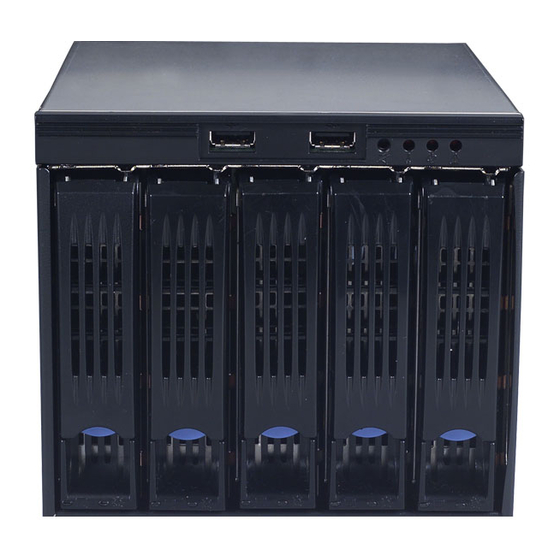
SK33502 Series 1-1 Front Panel Figure 1 Front panel A. Alarm Mute C. Indicator B. 3.5” Storage Drive Bay D. USB3.0 Product Overview │... -
Page 8: Back Panel
SK33502 Series 1-2 Back Panel Figure 2 Back panel USB Signal Connector D. Cooling Fan SATA 3.0 Connectors E. Fan Control Switch Fan Connector F. Power Connector Product Overview │... -
Page 9: Front Control Panel
SK33502 Series 1-3 Front Control Panel Figure 3 Front control panel Table 2 Front control panel Label ICON Indicator, button or connector Alarm Off Switch Temperature Alarm LED Fan Alarm LED HDD Alarm LED Product Overview │... -
Page 10: System Dimensions
SK33502 Series 1-4 System Dimensions Figure 4 Chassis dimensions Product Overview │... -
Page 11: System Level Environmental Specifications
SK33502 Series 1-5 System Level Environmental Specifications The following table defines the system level specifications under operating and non-operating environments. Table 3 System environmental specifications summary Parameter Specification Temperature Operating 5º C to 35º C (41º F to 95º F) -
Page 12: System Packaging
1-6 System Packaging The original Chenbro packaging, where the storage kit is delivered, is designed to provide protection to a fully configured chassis and tested to meet ISTA (International Safe Transit Association) Test Procedure 1A (2008). The packaging is also designed to be reused for shipment after system integration has been completed. -
Page 13: Installation And Removal
SK33502 Series 2. Installation and Removal SK33502 series supports up to 5 x 3.5” hot-swap SAS/SATA HDD, with additional cooling fan module as peripheral component. 2-1 Storage Kit Installation Figure 5 Storage kit installation-1 Figure 6 Storage kit installation-2 Installation and Removal│ 13... -
Page 14: Figure 7 Storage Kit Installation-3
SK33502 Series Figure 7 Storage kit installation-3 Insert the storage kit into the 5.25” 3-bay drive cage. Align the mounting holes and secure with screws as shown. Note: If the system chassis comes with tool-less installation rails for 5.25” bays, secure the storage kit with rails before inserting. -
Page 15: Hdd Tray Installation & Removal
SK33502 Series 2-2 HDD Tray Installation & Removal Figure 8 3.5” HDD installation (screw type) 1. Align the front of HDD with the anchor point on the tray. 2. Secure 3.5” HDD with tray by four screws as shown. Figure 9 3.5”... -
Page 16: Figure 10 2.5" Hdd/Ssd Installation (Screw Type)
SK33502 Series Figure 10 2.5” HDD/SSD installation (screw type) 1. Align the front of HDD/SSD with the anchor point on the tray. 2. Secure 2.5” HDD/SSD with the tray by four screws from the tray bottom. Figure 11 2.5” HDD/SSD removal (screw type) 1. -
Page 17: Storage Kit Fan Module Maintenance
SK33502 Series 2-3 Storage Kit Fan Module Maintenance Figure 12 Storage kit fan module installation-1 Figure 13 Storage kit fan module installation-2 Screw the fan with designated screws on the fan holder as a fan module. Align and press the fan module until it is fully attached on the rear cover. -
Page 18: Figure 14 Storage Kit Fan Module Removal-1
SK33502 Series Figure 14 Storage kit fan module removal-1 Figure 15 Storage kit fan module removal-2 1. Unplug the fan power connector. 2. Press and pull the fan module from both sides of the holder until it is detached from the rear cover. -
Page 19: Backplane
SK33502 Series 3. Backplane Each drive tray includes two LED indicators for drive activity and drive status. Light pipes integrated into the drive tray direct light emitted from LEDs mounted next to each drive connector on the backplane to the drive tray faceplate, making them visible from the front of the system. -
Page 20: Storage Backplane Options
SK33502 Series 3-1 Storage Backplane Options SK33502 series supports the below backplanes: 1 x 3.5” 5-port 12Gbps SAS/SATA passive backplane All available SAS/SATA backplanes include the following common features: 12Gbps SAS and 6Gbps SAS/SATA 29-pin SFF-8680 12Gbps rated drive interface connectors, providing both power and I/O signals to attached devices ... -
Page 21: 12Gbps Sas/Sata Backplane
SK33502 Series 3-2 3.5” 5-Port 12Gbps SAS/SATA Backplane Table 7 Backplane specifications Specification Host Interface SATA 7-pin HDD Interface SFF-8680 (SAS29) Hot-Swap Yes, allows users to replace devices online LED indicates storage device status Display Power LED – Off (Fault) –... -
Page 22: Figure 18 Backplane Rear View
DIP switch (SW1). Signal The event LED with red/black wire is located on front bezel of SK33502 series and can be configured through this pin header. Indicator Buzzer Buzzer will alarm when fan and temperature become abnormal. -
Page 23: Maintenance And Service
(Dead on Arrival) If the products are found Defect On Arrival, please contact Chenbro’s regional sales or CQE and indicate the defective status via email along with product photos and description. You may need to return the defective item by request.
Need help?
Do you have a question about the SK33502 Series and is the answer not in the manual?
Questions and answers