Table of Contents
Advertisement
Owner's/Installation Manual
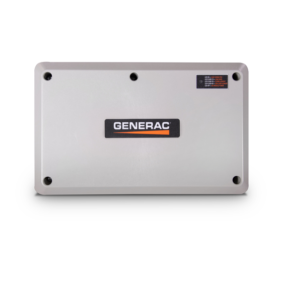
100A Smart Management Module
Para español , visita:
http://www.generac.com/service-support/product-support-lookup
Pour le français, visiter :
SAVE THIS MANUAL FOR FUTURE REFERENCE
Owner's/Installation Manual for SMM
MODEL: G007006-0
DATE PURCHASED:______________
Loss of life. This product is not intended to
be used in a critical life support application.
Failure to adhere to this warning could result
in death or serious injury.
WWW.GENERAC.COM
http://www.generac.com/service-support/product-support-lookup
(SMM)
WARNING
(000209b)
1-888-GENERAC
(1-888-436-3722)
i
Advertisement
Table of Contents
Troubleshooting

Summary of Contents for Generac Power Systems SMM
- Page 1 Failure to adhere to this warning could result in death or serious injury. (000209b) WWW.GENERAC.COM 1-888-GENERAC (1-888-436-3722) Para español , visita: http://www.generac.com/service-support/product-support-lookup Pour le français, visiter : http://www.generac.com/service-support/product-support-lookup SAVE THIS MANUAL FOR FUTURE REFERENCE Owner’s/Installation Manual for SMM...
- Page 2 WARNING CANCER AND REPRODUCTIVE HARM www.P65Warnings.ca.gov. (000393a) Owner’s/Installation Manual for SMM...
-
Page 3: Table Of Contents
How to Obtain Service ..........1 General Hazards ..........1 Section 2: General Information and Setup Load Management Options .........3 Application Considerations ........3 Smart Management Module (SMM) ....3 SMM and Carton Contents ........4 Setting Lockout ............5 Jumper Locations ..........5 Section 3: Installation, Tests, and Troubleshooting Electrical Specifications ........9... - Page 4 This page intentionally left blank. Owner’s/Installation Manual for SMM...
-
Page 5: Section 1: Introduction And Safety
Introduction DANGER Thank you for purchasing a Generac Smart Management Module (SMM). SMMs are designed to work together to Indicates a hazardous situation which, if not avoided, prevent a home standby generator from being over- will result in death or serious injury. - Page 6 Introduction and Safety This page intentionally left blank. Owner’s/Installation Manual for SMM...
-
Page 7: Section 2: General Information And Setup
Table 2-1. NOTE: For digital thermostats where a 24 VAC thermo- stat wire is not available, a SMM must be used to break the power at the HVAC load itself. Owner’s/Installation Manual for SMM... -
Page 8: Smm And Carton Contents
Table 2-2. Priority Decal (H)—Provided for recording priority of each module in installation. Install on electrical panel. NOTE: Recovery time is based on priority dial settings. Table 2-1. 009380 Figure 2-1. SMM Features and Controls Owner’s/Installation Manual for SMM... -
Page 9: Setting Lockout
Operating the unit at 50 Hz requires moving fre- subpanel of multiple branch circuits. quency jumper to “50 Hz” position. Proceed as follows to set SMM to enable standard lock- • For installations in areas with unstable utility out mode: power, set mode selector jumper to position “B”. - Page 10 NOTE: Actual test time varies depending on SMM priority setting. Use the Utility following formula to calculate test time: Time = (P-1) x 15 seconds, where P represents priority setting. Example: SMM Priority 6 test time = (6-1) x 15 seconds, or 75 seconds. Owner’s/Installation Manual for SMM...
- Page 11 General Information and Setup Figure 2-3. SMM Sequence of Operations Owner’s/Installation Manual for SMM...
- Page 12 General Information and Setup This page intentionally left blank. Owner’s/Installation Manual for SMM...
-
Page 13: Section 3: Installation, Tests, And Troubleshooting
1. Open carton. 3. See Figure 2-1. Hold SMM enclosure against 2. Remove and verify carton contents: mounting surface with arrows (G) pointing up, and • mark or drill four mounting holes (F). See Figure 3- for mounting dimensions if necessary. -
Page 14: Connections
Black (240 VAC - Load) Depth (in/mm) 5.3 / 136.9 White - Neutral (as required) 4. Install SMM enclosure to mounting surface using Green - Ground (as required) appropriate mounting screws or wall anchors. Black - Factory (PCB) Red - Factory (PCB) -
Page 15: Setting Priorities
Priority 7: Other circuits Priority 4: Clothes Dryer Priority 8: Other circuits 1. Set the priority of each SMM as desired (using the example configuration for reference). 2. Apply priority decal in a suitable location on electri- cal panel to record chosen priority designations. -
Page 16: Troubleshooting
The lockout switch is enabled and the During installation, it was determined that this load 6 second interval unit is on generator power. will be disabled during generator operation to prevent generator overload. Contact IASD for details. Owner’s/Installation Manual for SMM... - Page 17 Installation, Tests, and Troubleshooting This page intentionally left blank. Owner’s/Installation Manual for SMM...
- Page 18 Installation, Tests, and Troubleshooting This page intentionally left blank. Owner’s/Installation Manual for SMM...
- Page 20 ©2019 Generac Power Systems, Inc. Generac Power Systems, Inc. All rights reserved S45 W29290 Hwy. 59 Specifications are subject to change without notice. Waukesha, WI 53189 No reproduction allowed in any form without prior written 1-888-GENERAC (1-888-436-3722) consent from Generac Power Systems, Inc. www.generac.com...


Need help?
Do you have a question about the SMM and is the answer not in the manual?
Questions and answers