
Related Manuals for Wenglor SS2-00VA000R3


Summary of Contents for Wenglor SS2-00VA000R3
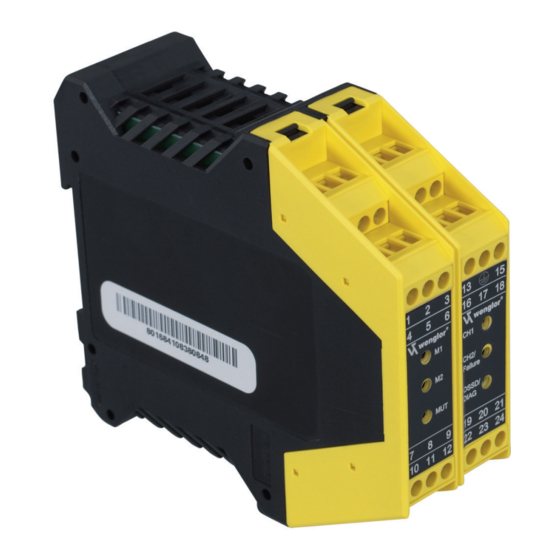
- Page 1 SS2-00VA000R3 Individual Safety Light Barrier Control Unit Operating instructions Available as PDF only Status: 02.05.2016 www.wenglor.com...
-
Page 2: Table Of Contents
Table of contents 1 General 1.1 Function and Use for Intended Purpose 1.2 Features 1.3 Applications Examples 1.3.1 Single Barrier Protection 1.3.2 Multiple Barrier Protection 1.3.3 Muting Function 1.4 Brief Explanation 1.5 Explanation of Utilized Symbols 2 Important Notes Concerning Use 2.1 General Comments 2.2 Securing the Danger Zone 2.3 Safety Clearance per EN ISO 13855... - Page 3 5 Outputs 5.1 Safety Outputs 5.2 Signal Control 5.3 Muting Signal Output 6 Muting 6.1 Basics 6.2 Connecting the Muting Sensors and the Muting Indicator 6.2.1 Muting Sensors 6.2.2 Muting Indicator 6.3 Selecting a Muting Duration 6.4 Mode of Operation 6.4.1 Muting Procedure 6.4.2 Muting Time Sequence 7 Override...
- Page 4 14 Technical Data 14.1 Safety Light Barriers 14.2 Individual Light Barrier Control Unit 15 Checklist 16 Certification 17 EC Declaration of Conformity 17.1 Declaration of conformity for Individual Safety Light Barrier Control Units SS2 36 17.2 Declaration of conformity for Safety Through Beam Sensor SL2 Due to the fact that they describe the operation of a safety device, these operating instructions are of a binding nature.
-
Page 5: General
The ESPE consists of an Individual Light Barrier Control Unit to which as many as four sensors can be connected. Use of the Individual Light Barrier Control Unit is only permitted with wenglor SL2-00 Light Barriers (see section 13 for order designations). Safety category 2 and Performance Level c is otherwise not assured. -
Page 6: Single Barrier Protection
1.3.1 Single Barrier Protection Use for securing robots 1.3.2 Multiple Barrier Protection Use for access monitoring 1.3.3 Muting Function Safety Light Barrier Receiver Safety Light Barrier Transmitter Muting Sensor Muting Sensor Receiver 1 Transmitter 2 Muting Sensor Muting Sensor Receiver 2 Transmitter 1... -
Page 7: Brief Explanation
1.4 Brief Explanation Contactor Monitoring An operating mode for which switching performance of the contacts at an external relay is dynamically monitored. The contacts must close fully within a specified period of time. Muting Mode Objects can be fed through the safety field without switching the safety output in this operating mode. OSSD (Output Signal Switching Device) The output of the contactless safety device which is connected to the machine controls. -
Page 8: Securing The Danger Zone
2.2 Securing the Danger Zone The danger zone must be secured by means of the light barriers alone, or by means of the light barriers in combination with additional mechanical safety devices. Reaching around, over and/or under the safety field must be prevented in any case. -
Page 9: Perpendicular Approach To The Safety Field
2.3.1 Perpendicular Approach to the Safety Field A minimum installation height of 750 mm from the reference level is required for the use of a light barrier C = Margin for penetration into the dan- ger zone before the safety device is tripped (never <... -
Page 10: Parallel Approach To The Safety Field
2.3.2 Parallel Approach to the Safety Field If this safety concept is used, the height of the safety field (H) may not be any greater than 1000 mm. If H is greater than 300 mm (or 200 mm for non-industrial applications, e.g. if children are present), one runs the risk of inadvertent, undetected access from underneath the safety field. -
Page 11: Mutual Interference Of The Light Barriers
After the light barriers have been mechanically mounted (see operating instructions for SL2-00), the SS2-00VA000R3 control unit is linked to the machine’s controller. The OSSD outputs must be connected to the machine’s safety circuit such that safety category 2 is still complied with. -
Page 12: Notes Regarding Connector Cables
If several control units are mounted next to each other, a minimum clearance of 2 cm must be maintained between the units in order to avoid overheating. The control unit must be provided with 24 V DC ± 20% supply power. External power supply must comply with EN 60204-1. -
Page 13: Connecting The Light Barriers
Color Status Operating State Muting sensor 1 unobstructed Yellow Muting sensor 1 obstructed Muting sensor 2 unobstructed Yellow Muting sensor 2 obstructed Normal operation Muting active Yellow • Override request Blinking • Muting failure (only with CH/Failure on) * Channel 1 unobstructed Green Channel 1 obstructed Failure detected *... -
Page 14: Connecting One Light Barrier
3.4.1 Connecting One Light Barrier Transmitter 1 Receiver 1 24 V DC SL2-00 SL2-00 24 V DC Muting Sensor 1 Muting Sensor 2 * See page 23 in section 6.2.1 ** See page 23 in section 6.2.2 Input/ Further Terminal Designation Output Information... -
Page 15: Connecting Two Light Barriers
3.4.2 Connecting Two Light Barriers Transmitter 2 Receiver 2 24 V DC SL2-00 SL2-00 24 V DC Transmitter 1 Receiver 1 SL2-00 SL2-00 24 V DC Muting Sensor 1 Muting Sensor 2 * See page 23 in section 6.2.1 ** See page 23 in section 6.2.2. Input/ Further Input/... -
Page 16: Connecting Three Light Barriers
3.4.3 Connecting Three Light Barriers 24 V DC Transmitter 3 Receiver 3 SL2-00 SL2-00 24 V DC 24 V DC Receiver 2 Receiver 1 Transmitter 2 Transmitter 1 SL2-00 SL2-00 SL2-00 SL2-00 24 V DC Muting Sensor 1 Muting Sensor 2 * See page 23 in section 6.2.1 ** See page 23 in section 6.2.2 Input/... -
Page 17: Connecting Four Light Barriers
3.4.4 Connecting Four Light Barriers 24 V DC 0 V 24 V DC Transmitter 3 Receiver 3 Transmitter 4 Receiver 4 SL2-00 SL2-00 SL2-00 SL2-00 24 V DC 24 V DC Transmitter 2 Receiver 2 Transmitter 1 Receiver 1 SL2-00 SL2-00 SL2-00 SL2-00... -
Page 18: Inputs
4 Inputs 4.1 Test Input A self-test is started at the control unit by applying 24 V DC to the test input (terminal 16). When the control unit’s safety inputs are activated, the control unit indicates that testing is being executed by shutting down the transmitters at the connected safety light barriers, and thus simulating penetration of the protected area. -
Page 19: Restart Inhibit
Input/ Further Input/ Further Terminal Designation Terminal Designation Output Information Output Information Muting input 1 p. 23, section 6.2 – – Muting input 2 p. 23, section 6.2 PE (ground) – – 24 V DC – – Acknowledgement input p. 18, section 4.2 Muting duration 1 p. -
Page 20: Contactor Monitoring
Input/ Further Input/ Further Terminal Designation Terminal Designation Output Information Output Information Muting input 1 p. 23, section 6.2 – – Muting input 2 p. 23, section 6.2 PE (ground) – – 24 V DC – – Acknowledgement input p. 18, section 4.2 Muting duration 1 p. - Page 21 • Control contacts K1-1 and K2-1 (terminal 20, block B) must be capable of switching a current of 20 mA and a voltage of 24 V DC. • In order to extend the service life of internal relays A and B, suitable interference suppressors should be used which are connected to the ends of the windings at L1 and L2 (block A).
-
Page 22: Outputs
• 0 V is applied to the output when muting is deactivated. • 24 V DC is applied to the output when muting is active. The muting indicator is an optical indicator lamp (e.g. wenglor’s SM0-00CA000C1). This output is also a PNP output. -
Page 23: Connecting The Muting Sensors And The Muting Indicator
• The sensors should detect the material only, and not the means of conveyance (e.g. pallet). Muting Sensor Muting Sensor sensors should detect load, and not the pallet. Material Pallet Conveyor Level • The material must be detected throughout the entire muting zone, i.e. the sensors’ output signals must remain unchanged. -
Page 24: Selecting A Muting Duration
Muting is only possible when the entire muting system is connected. This includes both muting sensors and the muting indicator. Any wenglor light barrier with an antivalent PNP output (the output must read out 24 V as long as the light beam is unobstructed) can be used as a muting sensor. -
Page 25: Muting Procedure
6.4.1 Muting Procedure The muting sensors must be arranged Transmitter Transmitter Muting Sensor 2 Muting Sensor 1 such that both of their beams are ob- Receiver structed by the object before it enters the safety field. Transmitter Receiver Receiver Muting Sensor 2 Muting Sensor 1 Transmitter Transmitter... -
Page 26: Muting Time Sequence
6.4.2 Muting Time Sequence Muting duration 30 sec., without exceeding the Time Limit max. 4 s Muting sensor 1 activated not activated Muting sensor 2 activated not activated Safety field unobstructed obstructed Muting < 30 s OSSD Muting duration 30 sec., with exceeding the Time Limit max. -
Page 27: Override With Continuous Command
7.2.2 Override with Continuous Command Override is activated when 24 V DC is applied to terminals 7 and 8 at the control module within a period of 400 ms, for example with a 2-pole key switch with spring return. Terminal 7 Terminal 8 Mode of Operation 0 V not connected... -
Page 28: Functions And Operation
8 Functions and Operation 8.1 Use of One Channel Meaning CH2/Failure OSSD/DIAG green red/green red/green/yellow Start-up test Channel obstructed, outputs off Channel unobstructed, outputs Yellow off, unit is waiting for restart Channel unobstructed, Green outputs on Indicates the status Yellow blinking System test of the channel (twice per second) -
Page 29: Diagnosis Information
9 Diagnosis Information If errors occur during use of the Individual Light Barrier Control Unit, the safety output is deactivated and the error LED blinks. Errors are eliminated in accordance with the following errors table. If an error occurs continuously, a trained specialist must be consulted. If necessary, the Individual Light Barrier Control Unit must be returned for repair. -
Page 30: Inspection Instructions
10 Inspection Instructions The inspections described below serve to confirm compliance with specified safety requirements set forth in na- tional/international regulations, in particular the safety requirements included in the machinery directive and the directive concerning safety and health requirements for the use of work equipment (EC conformity). The inspections also serve to detect influences which effect the device’s protective action, as well as any other un- usual ambient influences. -
Page 31: Environmentally Sound Disposal
11 Environmentally Sound Disposal SL2-00 Light Barriers and the SS2-00VA000R3 Individual Light Barrier Control Unit neither contain nor emit any ecologically harmful substances. They consume minimum amounts of energy and resources. Disposal: Devices which are no longer usable must be disposed of in accordance with all respectively valid, national waste disposal regulations. -
Page 32: Accessories And Order Designation
13 Accessories and Order Designation Connector Unit Individual Safety Light Barrier Control Unit without Muting: SS2-00VA000R2 Individual Safety Light Barrier Control Unit with Muting: SS2-00VA000R3 Approved Safety Light Barriers Type N Range 0...20 m Transmitter SL2-00NS000H2 Receiver SL2-00NE000H2 Accessories Muting Indicator... -
Page 33: Individual Light Barrier Control Unit
14.2 Individual Light Barrier Control Unit Safety Type Type 2 per EN 61496-1 Performance Level EN ISO 13849-1:2008 Category 2 PL c (in combination with SL2-00) Sicherheitsintegritätslevel SIL 1 per EN 61508 (only for SS2-00VA000R2) SILCL 1 per EN 62061 PFH d 3,16 ×... - Page 34 Supply power 24 V DC ± 20 %, SELV (IEC 60204)/PELV (IEC 60950) Power consumption < 5 W Safety outputs 2, NO contacts (2 A; 250 V) Fuse max. 4A, delay Response time < 30 ms (incl. Safety Light Barriers SL2) Switching current Signal control <...
-
Page 35: Checklist
Has the safety function been tested in accordance with the inspection instructions inclu- ded in the operating instructions? 16 Certification The safety device, consisting of an SS2-00VA000R3 Individual Light Barrier Control Unit and SL2-00NE000H2/ SL2-00NS000H2 Safety Light Barriers, has the following approvals: RoHS... -
Page 36: Ec Declaration Of Conformity
17 EU Declaration of Conformity 17.1 Declaration of conformity for Individual Safety Light Barrier Control Units SS2... -
Page 37: Declaration Of Conformity For Safety Through Beam Sensor Sl2
17.2 Declaration of conformity for Safety Through Beam Sensor SL2...
Need help?
Do you have a question about the SS2-00VA000R3 and is the answer not in the manual?
Questions and answers