Table of Contents
Advertisement
Quick Links
OWNER'S MANUAL
This Traulsen unit is built to our highest quality standards. We build our refrigerators and freezers this way as a matter of
pride. This philosophy has made Traulsen the leader in commercial refrigeration since 1938. We thank you for your choice and
confidence in Traulsen equipment and we know you will receive many years of utility from this equipment.
All Traulsen units are placed on a permanent record file with the service department. In the event of any future questions you
may have, please refer to the model and serial number found on the name tag affixed to the unit. Should you need service, call
us on our toll free number, 800-825-8220 between 7:30 am - 4:30 pm CST, Monday thru Friday. You may also log onto www.
traulsen.com for further information. It is our pleasure to help and assist you in every possible way.
COMPLETE THE FOLLOWING INFORMATION PRIOR TO UNIT INSTALLATION
INITIAL START DATE:
MODEL TYPE:
COMPANY/INDIVIDUAL NAME:
INSTALLER:
FORM NUMBER TR35944 (REV. 10-01-20)
Quality Refrigeration
Instructions for the installation, operation
and maintenance of Traulsen:
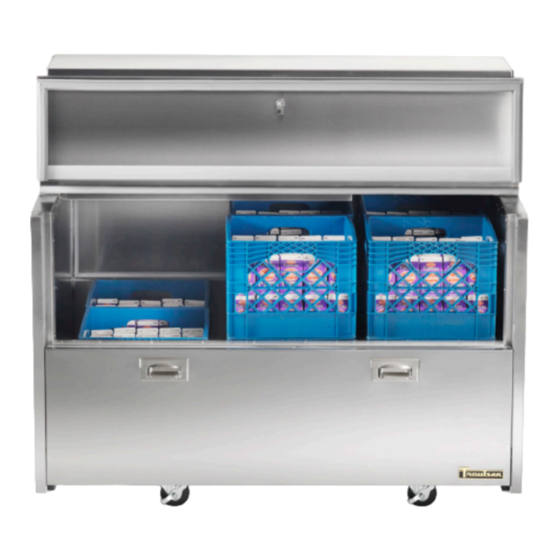
RMC Milk Cooler
RMC34, RMC49 & RMC58 Models
* For equipment produced after 10-2020 only
INSTALLER
SERIAL NO.
P/N 375-60324-00
Advertisement
Table of Contents

Related Manuals for Traulsen RMC Series

Summary of Contents for Traulsen RMC Series
- Page 1 * For equipment produced after 10-2020 only This Traulsen unit is built to our highest quality standards. We build our refrigerators and freezers this way as a matter of pride. This philosophy has made Traulsen the leader in commercial refrigeration since 1938. We thank you for your choice and confidence in Traulsen equipment and we know you will receive many years of utility from this equipment.
-
Page 2: Table Of Contents
238.1 g (238,1 g) SYS1 (REFM): Hi Press. (PRESH): 500psi 3.45 MPa (3,45 Mpa) Hi Press. (PRESH) • (S/N) Serial Number = The permanent ID# of your Traulsen Lo Press. (PRESL): 250 psi 1.72 Mpa (1,72 Mpa) Lo Press. (PRESL): unit SYS2 (REFA): R-404a 12.5oz... -
Page 3: Receipt Inspection
III. b - PACKAGING available (refer to the serial tag to determine correct unit Your Traulsen unit is shipped from the factory bolted to a voltage, see page 1). Make connections in accordance with sturdy wooden pallet in stretch wrapped material. -
Page 4: Operation
REV. DIMENSIONAL, MATERIAL OR PERFORMANCE CHARACTERISTICS OF SUCH PARTS AFTER 000-60330-00 APPROVAL BY TRAULSEN & CO. INC. GROUP OF VENDOR SAMPLES UNLESS AUTHORIZED IN DO NOT SCALE DRAWING IV. b - OPERATION DISPLAY INDICATORS WRITING BY TRAULSEN & CO. INC. - Page 5 V. CARE AND MAINTENANCE (continued) V. c - CLEANING THE CABINET SURFACES WARNING: DISCONNECT ELECTRICAL POWER SUPPLY BEFORE CLEANING ANY PARTS OF THE UNIT. Exterior stainless steel should be cleaned with warm water, mild soap and a soft cloth. Apply with a dampened cloth and wipe in the direction of the metal grain.
-
Page 6: Wiring Diagram
VI. WIRING DIAGRAM VI. a - WIRING DIAGRAM NOTE: Refer to the wiring diagram below for any service work performed by a qualified technician. -
Page 7: Control Basics
VII. CONTROL BASICS VII. c - INITIATING A DEFROST Your new Milk Cooler is equipped with a digital control, which precisely regulates operation. It is supplied from the factory Automatic defrost: completely ready for use and is located next to the Defrost starts automatically as soon as the time set with refrigeration system underneath the cover. -
Page 8: D) Configuration Parameters
VII. CONTROL BASICS (continued) VII. c - INITIATING A DEFROST (cont’d) VII. e - TECHNICAL DATA Resuming thermostatic cycle: Power supply When defrost is over, if DRN is greater than 0, all outputs TRL-002..W 100-240Vac ±10%, 50/60Hz, 3W will remain off for DRN minutes, in order for the ice to melt Relay output max loads (240Vac) completely and the resulting water to drain. - Page 9 VII. CONTROL BASICS (continued) RANGE DESCRIPTION -58..SPH Minimum limit for SP setting. SPL...180° Maximum limit for SP setting. SPL... SPH Setpoint (value to be maintained in the room). REF; HEA Refrigerating (REF) or Heating (HEA) control mode. 1...10° Thermostat OFF -> ON differential. 0...10°...
- Page 10 VII. CONTROL BASICS (continued) RANGE DESCRIPTION Defrost display mode. During defrost the display will show: RT: the real temperature; LT : the last temperature before defrost; SP : the current setpoint value; DEF : “dEF”. 0...60min Display delay. The display shows the information selected with parameter DDM during defrost and for DDY minutes after defrost termination.
- Page 11 VII. CONTROL BASICS (continued) RANGE DESCRIPTION IIH1 0... 10° Thermostat ON->OFF differential in mode 2. IIDF 0...250 Time interval among defrosts in mode 2 in x10 minutes. IIFC NON; Fan control in mode 2. See FCM. TMP; 1...5 Controller sensitivity for the automatic switchover from Group I to Group II (1=minimum, 5=maximum). 1…5 Controller sensitivity for the automatic switchover.
- Page 12 VII. CONTROL BASICS (continued) RANGE DESCRIPTION NON; AUX 1 output operation LGT; NON : output disabled (always off). 0-1; LGT : output enabled for light control. 2CU; 0-1 : the relay contacts follow the on/standby state of controller. 2EU; 2CU : output programmed for the control of an auxiliary compressor. ALO;...
-
Page 13: F) Componets And Wiring Diagram
VII. CONTROL BASICS (continued) VII. f - COMPONENTS AND WIRING DIAGRAM Control Wiring Diagram: Indications: Thermostat output Fan output Defrost output Activation of 2 patameter set Alarm Manual activation / Increase button Exit / Stand-by button -12-... - Page 14 VIII. SERVICE/WARRANTY INFORMATION (continued) VIII. a - TROUBLESHOOTING GUIDE FIND YOUR PROBLEM HERE REMEDY a.Check if cord & plug has been disconnected. 1. Condensing unit fails to start. b.Check control temperature setting. a.Are doors closing properly? 2. Condensing unit operates for prolonged periods or b.Dirty condenser or filter.
- Page 15 Is the condenser coil clean? Is the power switch on? If after checking the above items and the unit is still not operating properly, please contact an authorized Traulsen service agent: 4401 Blue Mound Road Fort Worth, TX 76106 (800) 825-8220.
-
Page 16: Service/Warranty Information
Purchaser. In the case of a nonconforming part, Purchaser must return the part to Traulsen within 30 days from the date of repair. Failure to return a claimed defective part to Traulsen within the 30 days will waive the right to the warranty claim. - Page 17 NOTES: -16-...
- Page 18 HOURS OF OPERATION: Monday thru Friday 7:30 am - 4:30 pm CST raulsen 4401 Blue Mound Road Fort Worth, TX 76106 Phone 800.825.8220 Fax 817.740.6757 traulsen.com Quality Refrigeration © 2020 Traulsen - All Rights Reserved...
Need help?
Do you have a question about the RMC Series and is the answer not in the manual?
Questions and answers