
Related Manuals for PMA rail line UNIFLEX CI 45

Summary of Contents for PMA rail line UNIFLEX CI 45
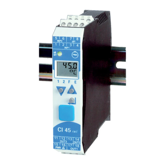
- Page 1 PMA Prozeß- und Maschinen-Automation GmbH UNIFLEX CI 45 universal transmitter CI 45 UNIFLEX CI 45 UNIFLEX Operating manual English 9499-040-71711 rail line Valid from: 06/2009...
- Page 2 Read the operating instructions Hint © 2004 PMA Prozeß- und Maschinen-Automation GmbH · Printed in Germany All rights reserved. No part of this document may be reproduced or published in any form or by any means without prior written permission from the copyright owner.
-
Page 3: Table Of Contents
Table of content 1. General ..........5 2. - Page 4 6.15 Analog output configuration ......33 6.15.1 Analog output ....... 33 6.15.2 Logic output .
-
Page 5: General
- preliminary - General General Thank you very much for buying a Universal Transmitter UNIFLEX CI 45. UNIFLEX CI 45 transmitters are suitable for precise, cost-efficient signal detection and processing. Every CI 45 is equipped with at least one universal input, one universal output and a relay. Optionally, the transmitter can be fitted with an additional relay. -
Page 6: Safety Hints
No operable controls are mounted inside the instrument, i.e. the operator must not open the unit. Modification, maintenance and repair may be carried out only by trained, authorized persons. For this purpose, the user is invited to contact the PMA service. Maintenance, repair, modification... -
Page 7: Cleaning
When opening the instruments, or when removing covers and components, live parts or terminals can be exposed. Caution When opening the instruments, electrostatically sensitive components can be exposed. The PMA service can be contacted as follows: PMA Prozeß- und Maschinen-Automation GmbH Miramstraße 87 D-34123 Kassel Tel. -
Page 8: Mounting
- preliminary - Mounting Mounting Montage / mounting Abmessungen / dimensions (0,08”) click Demontage / dismantling 111 (4,37”) 22.5 117.5 (4,63”) (0,87”) max. max. 55°C 95% rel. min. -10°C The unit is provided for vertical mounting on 35 mm top-hat rails to EN 50022. If possible, the place of installation should be exempt of vibration, aggressive media (e.g. -
Page 9: Connectors
Mounting Connectors The four instrument connectors are of the plug-in type. They plug into the housing from top or bottom and click in position. Releasing the connectors should be done by means of a screwdriver. Two connector types are available: •... -
Page 10: Electrical Connections
Electrical connections - preliminary - Electrical connections Connecting diagram (mV) INP2 INP1 RGND RGND Data A Data A Data B Data B RS 485 Logic OUT3 17 18 OUT1 90...260V AC OUT2 24V AC/DC Terminal connections Faulty connection might cause destruction of the instrument ! 1 Connecting the supply voltage Dependend on order 90 …... - Page 11 Electrical connections 2 Connecting input INP1 Input for the measurement value resistance thermometer (Pt100/ Pt1000/ KTY/ ...), 3-wire connection terminal: 1, 2, 3 resistance thermometer (Pt100/ Pt1000/ KTY/ ...), 4-wire connection terminal: 2, 3, 5, 6 potentiometer terminal: 1, 2, 3 current (0/4...20mA) terminal: 2, 3 voltage (-2,5...115/-25...1150/-25...90/ -500...500mV)
-
Page 12: Connecting Diagram
Electrical connections Connecting diagram Ò The instrument terminals used for the engineering can be displayed and printed out via BlueControl ( menu File \ Print preview - Connection diagram). Example Connecting diagram Connector 1 Name Description Process value x1 Measurement Frequency measurement Connector 2 Name... -
Page 13: Hints For Installation
Electrical connections Example: RS 485 interface with RS 485-RS 232 converter See documentation 9499-040-72011 Master z.B. / e.g. Converter RS 232-RS 485 (ADAM-4520-D) RGND DATA+ Data A LT 1 DATA- Data B LT 1 Data A Data B (R)+Vs (B)GND 10 Hints for installation Measurement and data lines should be kept separate from control and power supply cables. -
Page 14: Operation
Operation Operation Front view 1 Line 1: process value display 2 Line 2: display of unit / extended operating level / error list / Conf and PArA level values 3 Tare / sample & hold activated 4 Error list (2 x ô ), e.g. ·... -
Page 15: Operating Structure
Operation Operating structure The instrument operation is divided into four levels: 450. 3 Operating level ûC ô äüüü 450. 3 ô 1 2 F PASS PARA Parameter level äüüü 1 2 F ô 450. 3 PASS CONF äüüü Configuration level 1 2 F 450. -
Page 16: Display Line 2
Operation 5.4.2 Display line 2 Ò The value to be displayed continuously in the second LCD line can be selected via the BlueControl engineering tool. As default, the adjusted engineering unit is displayed. 450. 3 450. 3 Engineering unit as default setting Display of output OUT3 in % (with 55. -
Page 17: Slave Pointer Function
Operation 5.4.4 Slave pointer function The minimum and maximum input values are stored in the unit. 450. 3 450. 3 ûC ûC äüüü äüüü 1 2 F 1 2 F 450. 3 450. 3 502. 4 26. 7 äüüü äüüü 1 2 F 1 2 F The minimum input value is displayed as long as key Ì... -
Page 18: Extended Operating Level
Operation 5.4.6 Extended operating level The operation of important or frequently used parameters and signals can be allocated to the extended operating level. This facilitates the access, e.g. travelling through long menu trees is omitted, or only selected values are operable, the other data of the parameter level are e.g. -
Page 19: Functions
Functions Functions The signal data flow of transmitter CI 45 is shown in the following diagram: Linearization The input values of input INP1 or INP2 can be linearized via a table. By means of tables, e.g. special linearizations for thermocouples or other non-linear input signals, e.g. a container filling curve, are possible. -
Page 20: Input Scaling
Functions Ou. 3 2 Ou. 1 In. 1 In. 3 2 The same linearization table is used for input 1 and input 2. Input scaling Scaling of input values is possible. After any linearization, measurement value correction is according to the offset or two-point method. -
Page 21: Input Fail Detection
Functions For using the pre-defined scaling with thermocouples and resistance thermometers (Pt100), the settings for InL and OuL as well as for InH and OuH must correspond with each other. For resetting the input scaling, the settings for InL and OuL as well as InH and OuH must correspond. -
Page 22: Temperature Compensation, Measured Via Inp2 (Optional)
Functions - preliminary - Temperature compensation, measured via INP2 (optional) With thermocouple measurement via INP1, the required temperature compensation is possible by internal measurement of the compensation temperature via an external reference (external TC) or by measurement via INP2. With TC measurement via INP2, the following settings must be done: •... -
Page 23: Filter
- preliminary - Functions Filter A 1st order mathematical filter with adjustable time constant and bandwidth is built in. Output Input The filter bandwidth b. F x is the adjustable tolerance around the measured value within which the filter is active. Measurement value changes in excess of the adjusted bandwidth are not filtered. - Page 24 Functions - preliminary - A non-heated l probe is used, if the temperature is not constant. In this case, the temperature in addition to the probe mV value must be measured. For this purpose, any temperature measurement with analog input INP2 can be used.
-
Page 25: Counter (Optional)
Functions Displays With configuration for O measurement (see above), the oxygen content is displayed as process value with the selected unit (see above) on line 1. Max. 4 characters can be displayed. With display range overflow, “EEEE” is displayed . 20. -
Page 26: Frequency Input (Optional)
Functions Note that the counter end must be set to a lower value than the counter start (Cnt.S > Cnt.E) Resetting the counter cnts The counter can be reset to the start value by Reset via key combination Enter + increment key (keep the Enter key pressed and actuate the increment key) An activated limit value Lim1 …... -
Page 27: Arithmetic Functions
Functions Scaling The frequency input value can be scaled to a physical value in two points. 1st value: – input Frq. L (value specified in kHz) – physical value Ou. L 2nd value: – input Frq. H (value specified in kHz) –... -
Page 28: Tare Function (Optional)
Functions - preliminary - 6.11 Tare function (optional) Switching on the tare function sets the instantaneous input value to zero and measurement is continued with this offset. By switching off the tare function, the actual measurement value is displayed again . Measurement value Effective value 75. -
Page 29: Integrator Function
Functions 6.13 Integrator function The input signal can be totalized by means of a selectable integrator (ConF \ Func \ Fnc. 3 = 3). Function: Integrator with adjustable time constant (PArA \ Func \ t. I ) [specified in minutes] and adjustable input offset (PArA \ Func \ P. -
Page 30: Measured Value Monitoring
Functions 6.14.1 Measured value monitoring The signal to be monitored can be selected separately for each alarm in the configuration. The following signals are available: • Process value (display value) • Measurement value INP1 • Measurement value INP2 (option) • Counter / frequency measurement value (optional) Each of the 3 limit values Lim. - Page 31 Functions Alarm delay An alarm can become effective with a delay: the alarm output is set only after elapse of the adjusted delay time, provided that the limit value is still exceeded. Shorter alarms than the adjusted delay are ignored. Example: Alarm delay Signal change monitoring Another limit value processing function is signal change monitoring (per minute).
-
Page 32: Monitoring The Number Of Operating Hours And Switching Cycles
Functions H. 1 = OFF <L. 1 t [min] Lim.1 rot / red With measurement value or signal change with latch selected ( ConF / Lim / Fnc. x = 2, 4), the alarm relay remains set, until the alarm was reset in the error list, via di1 or via the interface (Lim1 ... -
Page 33: Analog Output Configuration
Functions 6.15 Analog output configuration 6.15.1 Analog output The two output signals (current and voltage) are available simultaneously. Adjust ConF / Out. 3 / O. t YP to select the output type which should be calibrated. ConF / Out. 3 : O. -
Page 34: Logic Output
Functions 6.15.2 Logic output The output can be used also as a logic output (O. t yp = 0). In this case, e.g. alarms or limit values can be output. 6.15.3 Transmitter power supply Two-wire transmitter power supply can be selected by adjusting O. t yp = 5. In this case, the analog output of UNIFLEX CI 45 is not available any more, but the input signal can be monitored or read out via the interface. -
Page 35: Frequency Output (Optional)
Functions 6.15.4 Frequency output (optional) The analog output signal for voltage can be selected also as a frequency output with setting: ConF / Out. 3 : O. t YP Out. 3 0...10V frequency output f [Hz] Frq. H Quelle source Frq. -
Page 36: Maintenance Manager / Error List
Error list: Name Description Cause Possible remedial action E. 1 Internal error, E.g. defective EEPROM Contact PMA service cannot be corrected Return instrument to manufacturer E. 2 Internal error, resettable E.g. EMC trouble Keep measuring and supply cables separate. Protect contactors by means of RC snubber circuits E. -
Page 37: Reset To Factory Setting
Functions Latched alarms Lim1/2/3 (E element displayed) can be acknowledged, i.e. reset via digital alarm di1. For Configuration, see page 46: ConF / LOGI / Err. r When an alarm is still pending, i.e. unless the error cause was removed ( E display blinks), latched alarms cannot be acknowledged and reset. -
Page 38: Configuration Level
Configuration level Configuration level Configuration survey Dependent on the device version and further adjusted configurations, configurationdata can be hidden. Data operable via the instrument front panel are shown in the following figure. Inp. 1 Inp. 1 Func Func Inp. 2 Inp. -
Page 39: Configurations
Configuration level Configurations Dependent on instrument version and configuration settings, display of values which are not required is suppressed. µ The entries marked with this symbol are selectable only, if the instrument option is fitted. Function selection Func Name Value range Description Function 1 µ... - Page 40 Configuration level Name Value range Description Special 0...450 Ohm Special 0...1600 Ohm Special 0...160 Ohm 0...20mA / 4...20 mA 0...10V / 2...10 V (Inp.1 only) Special (-2,5...115 mV) Special (-25...1150 mV) Special (-25...90 mV) Special (-500...500 mV) Special (-5...5 V) (Inp.1 only) Special (-10...10 V) (Inp.1 only) Special (-200..200 mV) Potentiometer 0...160 Ohm...
- Page 41 Configuration level Limit values Lim1 … Lim3 Name Value range Description Fnc. 1 Function of limit 1 (2, 3) Switched off (Fnc. 2 ) Measured value monitoring (Fnc. 3 ) Measured value monitoring + alarm status latch. A stored limit value can be reset via error list or a digital input ( ->...
- Page 42 Configuration level Name Value range Description Inf.2 Status message Inf.2 (number of switching cycles) (visible only with BlueControl!) Not active Active Output Out.3 (analog) Name Value range Description O. t YP Type of OUT3 Relay / logic (only visible with current/logic/voltage) 0 ...
- Page 43 Configuration level Name Value range Description O. S rc Signal source for analog output OUT3 (only visible with O.TYP=1..4 ) Not active Process value Measured value INP1 Measured value INP2 µ O. F AI Fail behaviour Upscale Downscale Inf.1 Status message Inf.1 (operating hours) (visible only with BlueControl!) Not active Active Inf.2...
- Page 44 Configuration level Name Value range Description Tare-function µ (function must be activated (CONF /FUNC / Fnc.3 = 1)) tArA No function (switch-over via interface is possible). Di1 switches. Limit 1 switches Limit 2 switches Limit 3 switches HoLd Sample & hold -function µ(function must be activated (CONF /FUNC / Fnc.3 = 2)) No function (switch-over via interface is possible).
- Page 45 Configuration level Name Value range Description Data parity on the interface µ PrtY no parity (2 stop bits) Even parity odd parity no parity (1 stop bit) Delay of response signal [ms] µ dELY 0...200 S. I F System interface µ D.
- Page 46 Configuration level Name Value range Description FrEq Switching 50/60 Hz (only visible with BlueControl!) Mains frequency 50 Hz Mains frequency 60 Hz ILat suppress error latch (only visible with BlueControl!) Enabled Blocked IExo Access to extended operation level (only visible with BlueControl!) Enabled Blocked Pass...
-
Page 47: Parameter Setting Level
Parameter setting level Parameter setting level Parameter survey Dependent on instrument version, display of parameters which are not required is suppressed. Adjustment The parameters can be adjusted by means of keys ÈÌ . • Transition to the next parameter is by pressing key ô. •... -
Page 48: Parameters
Parameter setting level Parameters µ The entries marked with this symbol are selectable only with the instrument option fitted. Function selection Func Name Value range Description -measurement µ tEmP 0...9999 Probe temperature for O 0,1...9999 Integrator-Zeitkonstante in Minuten µ -1999...9999 Integrator-Offsetµ... -
Page 49: Calibrating Level
Calibrating level Calibrating level Adaptation of the measurement value is possible in the calibrating menu ( CAL). Measured value correction ( CAL) is accessible only, if ConF / InP/ Corr = 1 or 2 was selected. Two methods are possible : •... -
Page 50: Offset Correction
Calibrating level Offset correction Offset correction shifts the input value by a pre-defined value. Parameter setting: ( ConF/ InP/ Corr =1 ): display standard setting offset correction On-line offset correction at the process is possible. 450. 3 ô 450. 0 PArA äüüü... -
Page 51: 2-Point Correction
Calibrating level 2-point correction display standard setting 2-point correction can change the offset and gradient 2-point correction the input curve. Parameter setting: ( ConF/ InP/ Corr = 2 ): 2-point correction is possible off-line by means an input signal simulator, or on-line in 2 steps: correct one value first and the second value subsequently, e.g. -
Page 52: Bluecontrol Engineering Tool
Ò BlueControl engineering tool Ò â The BlueControl engineering tool is the projecting environment for the PMA BluePort instrument series and for the rail line series. The following versions with different functionalities are available: Functions Mini Basic Expert*... -
Page 53: Versions
Operating instructions for CI 45 English 9499-040-71711 Interface description MODBUS rail line German 9499-040-72018 Interface description MODBUS rail line English 9499-040-72011 BlueControl® Mini German/English www.pma-online.de BlueControl® with basic licence rail line German/English 9407-999-12001 BlueControl® with expert licence rail line German/English 9407-999-12011 UNIFLEX CI 45... -
Page 54: Technical Data
Technical Data Technical Data Measurement span The BlueControl® software enables the internal characteristic INPUTS curve for the KTY 11-6 temperature sensor to be adapted. Divided into ranges 0...4500 W UNIVERSAL INPUT INP1 Physical measurement range: Resolution: >15 bits Current and voltage measurement Decimal point: 0 to 3 decimals (Table 3) - Page 55 Technical Data Table 2: Resistive inputs Type Sensor current Measurement range Error Typical resol. ß 1 K Pt100*** -200...100(150)°C -328...212(302)°F 0.05 K ß 2 K Pt100 -200...850°C -328...1562°F 0.05 K ß 2 K Pt1000 -200...850°C -328...1562°F 0.05 K ß 2 K KTY 11-6* -50...150°C -58...302°F...
- Page 56 - preliminary - Technical Data Number of electrical for I= 1A/2A: Control input ? 800.000 / 500.000 switching cycles: Configurable as a direct or inverse switch or key! (at ~ 250V (resistive load)) Functions: Locking front operating, Note: resetting of latched alarms, slave pointers, If the relays OUT1 and OUT2 operate external contactors, these integrator;...
- Page 57 Technical Data POWER SUPPLY Frequency output Depending on ordered version Output by means of voltage output AC supply Frequency range: 0, 0.25 ...1000 Hz (square-wave signal) Voltage: 90...260 V AC Output value: scalable Frequency: 48...62 Hz Level: 0 / 11,5V Consumption: approx.
- Page 58 Technical Data Permissible temperatures Electrical safety For specified accuracy: -10...55°C Complies with EN 61010-1: Warm-up time: < 20 minutes Over-voltage category II ß 0.05% / 10 K Temperature effect: Contamination degree 2 add. influence to cold Protection class II ß 0.75 K / 10 K junction compensation: Operating limits: -20...60°C...
-
Page 59: Index
Index - limit 29 - 32 - linearization 19, 46 - 2-point-correction - logic - output - accessories - maintenance - additional equipment - maintenance manager - alarm delay - maximum value - analog output - minimum value - applications - mounting 8 - 9 - arithmetic functions... - Page 60 9499- 040- 71711 Subject to alterations without notice © PMA Prozeß- und Maschinen-Automation GmbH Änderungen vorbehalten P.O.B. 310 229, D-34058 Kassel, Germany Sours réserve de toutes modifications Printed in Germany 9499-040-71711 (06/2009)
Need help?
Do you have a question about the rail line UNIFLEX CI 45 and is the answer not in the manual?
Questions and answers