
Related Manuals for PMA UNIFLEX SG45

Summary of Contents for PMA UNIFLEX SG45
- Page 1 PMA Prozeß- und Maschinen-Automation GmbH Transmitter UNIFLEX SG45 + INP - +SENSE- UNIFLEX SG 45 UNIFLEX SG 45 Operating manual English 9499-040-82311 valid from: 10/2009...
- Page 2 Read the operating instructions Note © 2008 · PMA Prozeß- und Maschinen-Automation GmbH · Printed in Germany All rights reserved · No part of this document may be reproduced or published in any form or by any means without prior written permission from the copyright owner.
-
Page 3: Table Of Contents
Content 1. General ..........5 2. - Page 4 7. Configuration level........34 7.1 Configuration survey .
-
Page 5: General
General General Thank you very much for buying a transmitter for load cells, strain gauges, and melt pressure sensors UNIFLEX SG 45 . The UNIFLEX SG 45 transmitters are suitable for precise, cost-efficient contol tasks in all industrial applications. Every SG 45 is equipped with a strain gauge signal input, an universal output and two relays. Optionally the tranmitter can be fitted with various interfaces. - Page 6 General SG 45...
-
Page 7: Safety Hints
Safety hints Safety hints This unit was built and tested in compliance with VDE 0411-1 / EN 61010-1 and was delivered in safe condition. The unit complies with European guideline 89/336/EWG (EMC) and is provided with CE marking. The unit was tested before delivery and has passed the tests required by the test schedule. To maintain this condition and to ensure safe operation, the user must follow the hints and warnings given in this operating manual and operate this instrument in compliance with the instructions given in this manual. -
Page 8: Maintenance, Repair And Modification
There are no operable elements inside the device, so the user must not open the unit Modification, maintenance and repair work may be done only by trained and authorized personnel. For this purpose, the PMA service should be contacted. Warning When opening the units, or when removing covers or components, live parts and terminals may be exposed. -
Page 9: Mounting
Mounting Mounting Montage / mounting Abmessungen / dimensions (0,08”) click Demontage / dismantling 111 (4,37”) 22.5 117.5 (4,63”) (0,87”) max. max. 55°C 95% rel. min. -10°C The unit is provided for vertical mounting on 35 mm top-hat rails to EN 50022. If possible, the place of installation should be exempt of vibration, aggressive media (e.g. -
Page 10: Connectors
Mounting Connectors The four instrument connectors are of the plug-in type. They plug into the housing from top or bottom and click in posi - tion (audible latching). Releasing the connectors should be done by means of a screwdriver. Two connector types are available: •... -
Page 11: Electrical Connections
Electrical connections Electrical connections Connecting diagram EX - EX + INP1 + Sense - RGND RGND Data A Data A Data B Data B RS 485 OUT3 17 18 OUT1 ~90-260V OUT2 ~24V 17 18 System Terminal connections Faulty connection might cause destruction of the instrument ! 1 Connecting the supply voltage Dependent on order •... - Page 12 Electrical connections 3 Connecting input di1 Digital input control input (as a potentialfree contact) terminals: 7, 8 4 Connecting outputs OUT1 / OUT2 (optional) Relay outputs max. 250V/2A NO contacts with a common terminal. • OUT1 terminals: 17, 18 • OUT2 terminals: 17, 14 5 Connecting output OUT3...
-
Page 13: Connecting Diagram
Electrical connections Connecting diagram Ò The instrument terminals used for the engineering can be displayed and printed out via BlueControl ( menu File \ Print preview - Connection diagram). Example: Device1.bct Connecting plan Terminal connector 1 Name Description Sensor supply Probe cable Process value X1 Terminal connector 2... -
Page 14: Connection Examples
Electrical connections Connection examples Example: Connection load cell with 4 or 6-wire bridge Sense+ 2 SENSE + Excitation+ + INP - 6 INP - +SENSE- Ausgang 5 INP + Excitation- 4 EX- 3 SENSE - Sense- only with 6-wire bridge After initialization, a test for connection of the sense signal is made automatically (6-wire connections ) Example: Connection of a (melt) pressure sensor in 4-wire technology with a calibrating resistor Excitation... -
Page 15: Hints For Installation
Electrical connections Hints for installation Measurement and data lines should be kept separate from control and power supply cables. Sensor measuring cables should be twisted and screened, with the screening connected to earth. External contactors, relays, motors, etc. must be fitted with RC snubber circuits to manufacturer specifications. - Page 16 Electrical connections UL approval (optional) SG 45...
-
Page 17: Operation
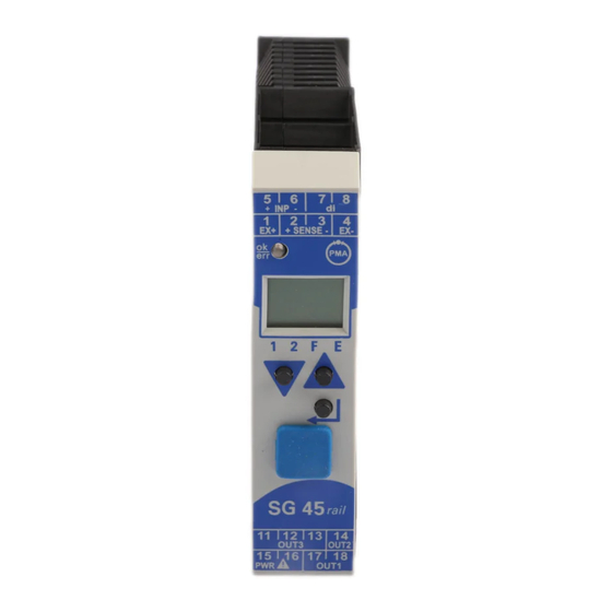
Operation Operation Front view 1 Line 1: process value display + INP - 2 Line 2: display of unit / extended operating level / error list / +SENSE- Conf and PArA level values Tare / sample & hold activated 4 Error list (2 x ô ), e.g. ·... -
Page 18: Operating Structure
Operation Operating structure The instrument operation is divided into four levels: 450. 3 ô äüüü 450. 3 ô 1 2 F PASS Operating level InSt äüüü 1 2 F Installation and ô 450. 3 Calibrating level PASS PARA See page äüüü... -
Page 19: Displays In The Operating Level
Operation Displays in the operating level 5.4.1 Display line 1 The display value is the value resulting from function.1, function.2, function.3 handling. It is also called process value (see also section/page 23.) 5.4.2 Display line 2 The value to be displayed continuously in the second LCD line can be selected from different values via the Ò... -
Page 20: Slave Pointer Function
Operation 5.4.4 Slave pointer function The minimum and maximum input values are stored in the unit. 450. 3 450. 3 ûC ûC äüüü äüüü 1 2 F 1 2 F 450. 3 450. 3 26. 7 502. 4 äüüü äüüü 1 2 F 1 2 F The minimum input value is displayed as long as key Ì... -
Page 21: Extended Operating Level
Operation 5.4.6 Extended operating level The operation of important or frequently used parameters and signals can be allocated to the extended operating level. This facilitates the access, e.g. travelling through long menu trees is omitted, or only selected values are operable, the other data of the parameter level are e.g. - Page 22 Operation SG 45 Displays in the operating level...
-
Page 23: Functions
Functions Functions The signal data flow of transmitter SG 45 is shown in the following diagram: Measuring input INP Measuring range Configuration S. t YP 0.5 mV/V (5 mV) 1 mV/V (10 mV) 2 mV/V (20 mV) 4 mV/V (40 mV) Input for bridge circuit (3 possibilities): ·... -
Page 24: Input Scaling
Functions Input scaling Scaling of input values is possible. This correction influences the measured value after an eventually executed linearization. Specification of the input value of the lower and upper scaling point is in units of the relevant physical quantity. phys. -
Page 25: Linearization
Functions Linearization The input values of the input can be linearized via a table. This feature can be used e.g. to realize linearizations to specification for non-linear curves. The “ Lin” table is always used when S. L in = 1: “Linearization to specification” is set in INPm. The input signals are filled in in units of the physical quantity (scaling result). -
Page 26: Filter
Functions Filter A 1st order mathematical filter with adjustable time constant and bandwidth is built in. Output Input The filter bandwidth b. F 1 is the adjustable tolerance around the measured value within which the filter is active. Measurement value changes in excess of the adjusted bandwidth are not filtered. Substitue value for inputs If a substitute value for an input is activated, this value is used for further calculation with a sensor fault, independent of the selected input function. -
Page 27: Set Zero
Functions Set zero The function is enabled during configuration (Func r Func. 1 =1. Due to its effect, the display is reset to zero, when e.g. small rest quantities are still on the scale and cannot be re - moved immediately. To prevent excessive use of the zero setting function, the zero offset (page 30) can be provided with an alarm. -
Page 28: Integrator Function
Functions 6.10 Integrator function The input signal can be totalized by means of a selectable integrator (ConF \ Func \ Fnc. 3 = 3). Function: Integrator with adjustable time constant (PArA \ Func \ t. I ) [specified in minutes] and adjustable input offset (PArA \ Func \ P. -
Page 29: Limit Value Processing
Functions 6.11 Limit value processing Max. three limit values can be configured for the outputs. Generally, each one of outputs Out. 1 ... Out. 2 can be used for limit value or alarm signalling. Several signals allocated to an output are linked by a logic OR function. 6.11.1 Input value monitoring The signal to be monitored can be selected separately for each alarm in the configuration. - Page 30 Functions Alarm delay An alarm can become effective with a delay: the alarm output is set only after elapse of the adjusted delay time, provided that the limit value is still exceeded. Shorter alarms than the adjusted delay are ignored. Example: Alarm delay Signal change monitoring Another limit value processing function is signal change monitoring (per minute).
- Page 31 Functions With measurement value or signal change with latch selected ( ConF / Lim / Fnc. x = 2, 4), the alarm relay remains set, until it was reset in the error list, This alarm can be reset via: di1 or a limit value a key combination or via interface (Lim1 ...
-
Page 32: Monitoring The Number Of Operating Hours And Switching Cycles
Functions 6.11.2 Monitoring the number of operating hours and switching cycles Operating hours The number of operating hours can be monitored. When reaching or exceeding the adjusted value, signal InF.1 is acti - vated (in the error list and via an output, if configured). The monitoring timer starts when setting limit value C.Std. -
Page 33: Analog Output Configuration
Functions 6.12 Analog output configuration 6.12.1 Analog output The two output signals (current and voltage) are available simultaneously. Adjust ConF / Out. 3 / O. t YP to se- lect the output type which should be calibrated. ConF / Out. 3 : O. -
Page 34: Analog Output Forcing
Functions 6.12.2 Analog output forcing Ò By adjusting f.Out = 1 (only via BlueControl ), the output can be configured for value input via interface, or by means of an input value at extended operating level (=Forcing). This setting can be used also for e.g. testing the cables and units connected in the output circuit. This function can also realize a setpoint potentiometer. -
Page 35: Maintenance Manager / Error List
Description Cause Possible remedial action Name E. 1 Internal error, cannot be E.g. defective EEPROM Contact PMA service corrected Return device to manufacturer Internal error, resettable E.g. EMC trouble Keep measuring and supply cables separate. E. 2 Protect contactors by means of RC snubber cir- cuits E. -
Page 36: Detection And Display Of Sensor And Wiring Errors
Functions Latched alarms Lim1/2/3 (E-element displayed) can be acknowledged, i.e. reset via digital alarm di1. For Configuration, see page 41: ConF / LOGI / Err. r When an alarm is still pending, i.e. unless the error cause was removed ( E display blinks), latched alarms cannot be acknowledged and reset. -
Page 37: Resetting To Factory Setting
Functions 6.15 Resetting to factory setting In case of faulty configuration, the SG 45 can be reset to the default manufacturers condition. + Power on switch on power supply For this, the operator must keep the keys increment and decrement pressed during power-on. torY Then, press key increment to select Confirm factory resetting with Enter and the copy... -
Page 38: Configuration Level
Configuration level Configuration level Configuration survey Dependent on the device version and further adjusted configurations, configurationdata can be hidden. The data which can be operated via the front panel are shown below. OUt. 1 Func Inp. 1 OUt. 2 OUt. 3 LOGI othr ô... -
Page 39: Configurations
Configuration level Configurations Dependent on device version und adjusted configurations values not needed become hidden. µ Entrys marked with this symbol are selectable only with existing device-option. Selection of functions Func Name Value range Description Fnc1 Function 1 No function Zero setting Fnc. - Page 40 Configuration level Outputs Out.1 and Out.2 (relay) Name Value range Description O. A ct Direction of operation OUT1 Direct / normally open Inverse / normally closed Lim. 1 Signal limit 1 not active active Lim. 2 Signal limit 2 not active active Lim.
- Page 41 Configuration level Signal definition LOGI Name Value range Description di. F n Function of inputs (valid for all inputs) direct inverse toggle key function (adjustable for 2-point-operation with interface and di1) Local / remote switchover (Remote: Adjustment of all values via the front panel is blocked) Interface only (local, value adjustment via front-panel controls is possible) always active (remote) di1 switches...
- Page 42 Configuration level Name Value range Description rES. H Reset maximum value Interface only di1 switches Limit 1 switches Limit 2 switches Limit 3 switches Enter/Inc keys switch Ü Enter/Dec key switch Ü rES. I Reset Integrator Interface only di1 switches Limit 1 switches Limit 2 switches Limit 3 switches...
- Page 43 Configuration level Miscellaneous (other) Name Value range Description S. I F System interfaceµ switched off switched on Address on the interface µ Addr 1...247 Baudrate on the interface µ bAud 2400 Baud 4800 Baud 9600 Baud 19200 Baud 38400 Baud PrtY Parity of data on the interface µ...
- Page 44 Configuration level Name Value range Description Ò Block error memory (only visible with BlueControl ILat Released Blocked Ò Password (only visible with BlueControl Pass OFF...9999 Ò IPar Block parameter level (only visible with BlueControl Released Blocked Ò ICnf Block configuration level (only visible with BlueControl Released Blocked Ò...
-
Page 45: Parameter-Level
Parameter-level Parameter-level Parameter-survey Dependent on device version und adjusted configurations values not needed become hidden. The data which can be operated via the front panel are shown below. Adjustment: • Parameters can be adjusted with ÈÌ - keys. Stepping to the next parameter by pressing the ô - key. •... -
Page 46: Parameters
Parameter-level Parameters Selection of functions Func Name Value range Description t. I 0,1...9999 Integrator timeconstant (in minutes) P. I -1999...9999 Integrator-Offset Inputs InP.1 Name Value range Description InL. 1 Lower input value (Span start) -1999...9999 Oul. 1 Lower output value -1999...9999 InH. -
Page 47: Installation And Calibration
Installation and calibration Installation and calibration When the operating voltage is applied to SG45 after connecting e.g. the load cells, the unit starts running. An automatic check for connection of the Sense lines takes place. This check is done also after configuration changes. ô... -
Page 48: Calibration ( Cal)
Installation and calibration Calibration ( CAL) Before calibration, allow the unit to warm up (see Technical Data on page 54). After delivery, a % value is displayed as a measured value (related to the adjusted measuring range). For this reason, the Uniflex SG 45 must be adapted to its measuring task accordingly. To adapt the unit, realize the cal - ibration correctly. -
Page 49: Scaling ( Scal)
Installation and calibration Scaling ( SCAL) · (Menu with SEt – CAL – SCAL – End) q Þ possibility for read out of the scaling determined under CAL or for direct input of scaling parameters InL. 1 ¿ OuL. 1 ¿ InH. -
Page 50: Engineering Tool Bluecontrol Ò
Personal assistant function * on request The mini version is - free of charge - at your disposal as download at PMA homepage www.pma-online.de or on the PMA-CD (please ask for). At the end of the installation the... -
Page 51: Versions
MODBUS rail line english 9499-040-72011 Additional devices: Description Order-No. PC-Adapter for BluePort® interface 9407-998-00001 ® BlueControl Mini www.pma-online.de ® BlueControl with Basic - licence rail line 9407-999-12001 ® BlueControl with Expert - licence rail line 9407-999-12011 SG 45... -
Page 52: Technical Data
Technical data OUTPUTS Technical data RELAY OUTPUTS OUT1, OUT2 INPUTS Contact type: 2 normally open with common contact connection SIGNAL INPUT INP Max. contact rating: 500 VA, max. 250 V, max. 2A at 48...62 Hz, ohmic load Accuracy: 0,01% at 25°C Min. - Page 53 Technical data GALVANIC ISOLATION BLUEPORT FRONT INTERFACE ® Connection to the controller front via a PC adapter (see ‘Additional System RS 485 Accessories’). The BlueControl ® software enables the KS 45 to be Input INP configured, parameters set, and operated. di 1 (contact) Power BUS INTERFACE (OPTIONAL)
- Page 54 Technical data ENVIRONMENTAL CONDITIONS GENERAL Protection mode Housing front Front panel: IP 20 Material: Polyamide PA 6.6 Flammability class: VO (UL 94) Housing: IP 20 Terminals: IP 20 Connecting terminals Material: Polyamide PA Permissible temperatures Flammability class: V2 (UL 94) for screw terminals V0 (UL 94) for spring-clamp terminals and For specified accuracy: -10...55°C...
-
Page 55: Index
Index Index maximum value ....19 minimum value ....19 Accessories . - Page 56 9499- 040- 82311 Subject to alterations without notice © PMA Prozeß- und Maschinen-Automation GmbH Änderungen vorbehalten P.O.B. 310 229, D-34058 Kassel, Germany Sous réserve de toutes modifications Printed in Germany 9499-040-82311 (10/2009)
Need help?
Do you have a question about the UNIFLEX SG45 and is the answer not in the manual?
Questions and answers