Advertisement
Quick Links
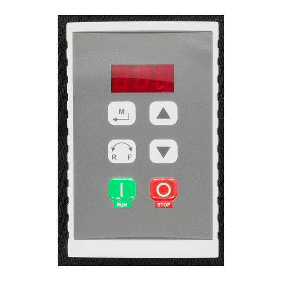
SCL/SCM SERIES REMOTE KEYPAD
INSTRUCTIONS
(Manual Number: KM01A-e1)
Th e SCL/SCM Series Remote Keypad option (#844-240) allows the SCL/SCM
Series drive to be programmed and controlled from up to 8 feet away (typically
from the front of the enclosure that houses the SCL/SCM drive). When properly
mounted, the remote keypad is rated up to NEMA 4X.
In addition to the functions available on the front of the SCL/SCM drive, the
remote keypad has Start/Stop and Forward/Reverse functions.
NOTE: Th e Remote Keypad option will only work with SCL/SCM drives that have
parameter version "320" or higher. Th e parameter version appears momentarily
on the drive display when it is powered up, and also appears on a sticker on the
drive's heatsink.
WARNING!
If OEM mode is selected (using Parameter 48), and if the OEM Default settings
for Parameters 11, 12, and 14 are not "13", "21", and "02" respectively, the remote
keypad will be disabled, and the STOP key WILL NOT work. Refer to the SCL/
SCM manual for more information on OEM Default settings.
1.
PARTS LIST
Th e SCL/SCM Remote Keypad kit includes the following parts:
(1)
Remote Keypad
(2)
Self-tapping Mounting Screws
(1)
Eight foot cable
NOTE: Th e supplied cable is unshielded and can only be used in low-noise
environments. In high-noise environments, use Belden 9842, Carol C4842, or
equivalent (24 gage minimum) wire only. Th e maximum cable length that can
be used is 8 feet.
3.
MOUNTING THE REMOTE KEYPAD
Th e diagram below illustrates how to mount the remote keypad to a panel. Use the
template in Section 2 to mark the location of the mounting holes on the panel.
PANEL
GASKET
• 630 Douglas Street • Uxbridge, MA 01569 • Ph: (800) 217-9100 • Ph: (508) 278-9100 • Fax: (508) 278-7873 • www.actechdrives.com
(1)
Gasket
(1)
Instruction Sheet
MOUNTING
SCREWS
REMOTE
KEYPAD
2.
SCL/SCM REMOTE KEYPAD TEMPLATE
Hold this page against the panel where the remote keypad is to be mounted, and
use a center punch to mark the location of the holes. Th e dotted line is the outline
of the remote keypad.
UP
1.32"
1.57"
1.38" to 1.5"
hole
Max Depth = 0.72"
4.
WIRING CONNECTIONS
WARNING!
Improper wiring may result in damage to the Remote Keypad. Keep the remote
keypad cable away from power wiring.
Th e Belden and Carol cables specifi ed consist of two twisted pairs. Make sure
one twisted pair is used for connections to 13B and 13E, and the other is used for
connections to 11 and 2. Do not mix connections between twisted pairs.
NOTE: Th e supplied cable is unshielded and can only be used in low-noise
environments. In high-noise environments, use Belden 9842, Carol C4842, or
equivalent (24 gage minimum) wire only. Th e maximum cable length that can
be used is 8 feet.
1
2
5
6
Cable included with kit
does not have a shield
REMOTE KEYPAD
(BACK VIEW)
1/8" hole
3.38"
1/8" hole
2.19"
11
13A 13B
13E
UP
13B
13E
11
2
25
Advertisement

Related Manuals for Lenze AC Tech 844-240


Summary of Contents for Lenze AC Tech 844-240
- Page 1 SCL/SCM SERIES REMOTE KEYPAD SCL/SCM REMOTE KEYPAD TEMPLATE INSTRUCTIONS Hold this page against the panel where the remote keypad is to be mounted, and (Manual Number: KM01A-e1) use a center punch to mark the location of the holes. Th e dotted line is the outline of the remote keypad.
- Page 2 SETTING UP THE SCL/SCM DRIVE REMOTE KEYPAD FUNCTIONS Th e M key and the L and M keys on the remote keypad function the same as the To set up the SCL/SCM drive to work with the Remote Keypad, the following Mode button and the L and M buttons on the drive.
Need help?
Do you have a question about the AC Tech 844-240 and is the answer not in the manual?
Questions and answers