Advertisement
Quick Links
Advertisement

Related Manuals for Foldcraft Plymold Contour Wall Style Adjustable

Summary of Contents for Foldcraft Plymold Contour Wall Style Adjustable
- Page 1 Contour Wall Style Adjustable Z000000201 Revised 04 17 2015 ...
-
Page 2: Unpacking Your Shipment
Contour Page 2 of 9 Unpacking Your Shipment Unpack and iden fy each component in each box that you received. If your shipment is missing parts, or too many parts were shipped, please contact Plymold. Components CONTOUR SEAT ADJUSTABLE WALL STYLE FRAME TABLE TOP SINGLE SEAT HARDWARE KEP NUT 1/4‐20 1/4—20 ELBO BOLT REAR SEAT HOOK FRONT SEAT HOOK FRAME HARDWARE MACHINE SCREW HEX HEAD CAP SCREW 1/4‐ HEX HEAD CAP SCREW 3/8‐ Nylon Insert Lock WASHER 3/8” 1/4‐20 x 5/8” 20 x 3/4” 16 x 3 3/4” Nut 3/8‐16 FLOOR AND TABLE HARDWARE ADJUSTABLE PLASTIC SCREW #10 X 1” PLASTEC FLOOR ANCHOR GLIDE (A) Cap Screw Bu on Head WALL STYLE ADA FRAME 3/8‐16 x 3‐1/2” (ADA FRAME ONLY) ... -
Page 3: Tools Required
Contour Page 3 of 9 Tools Required Screw Gun w/#2 PHILLIPS Bit Pencil or Marker Hammer Drill 4” Bit Screw Driver 7/16” Socket 7/16” Ratchet and Open End Wrench Level Tape Measure ... - Page 4 Contour Page 4 of 9 Assembly Step 1: Glide Assembly ‐ Adjustable Wall Style Frame a. Assemble a thread‐in glide into the insert in each of the four (4) legs. (A) (A) Step 2: Frame Assembly a. Using 3/8”‐16 x 3 3/4” hex head cap screw, 3/8‐16 lock nut and 3/8” washers, assemble the seat support leg to the main support frame. Note: Center holes are for 24” wide top spacing. b. Repeat step a with the second seat support leg. c. A ach the can lever to the main support frame using 1/4‐20 x 5/8” machine screws on the bo om. Use the 1/4‐20 x 3/4” hex head cap screws with a 1/4‐20 kep nut on the bo om. ...
- Page 5 Contour Page 5 of 9 Assembly Step 1: Glide Assembly ‐ ADA Wall Style Frame a. Assemble a thread‐in glide into the insert in each of the four (6) legs. (A) (A) (A) (A) (A) Step 2: Frame Assembly a. Using 3/8”‐16 x 3 3/4” hex head cap screw, 3/8‐16 Lock Nut and 3/8” washers, assem‐ ble the seat support leg to the main sup‐ port frame. Note: Use outside holes, no adjustment. b. A ach support leg using 3/8‐16 x 3‐1/2” cap screw bu on head and 3/4‐16 lock nuts. Note: Place bu on head on inside of leg. c. A ach table angle to main support using 1/4‐20 x 2.0” hex head screws and 1/4‐20 kep ...
- Page 6 Contour Page 6 of 9 Assembly Step 3: Assemble Seat to Frame a. Locate single seat hardware kit. b. Posi on seat on end and insert front hooks. c. Posi on the seat over the frame by pping the edge of the seat forward and pulling the seat into place. d. A ach elbow bolts to front seat hooks and hand ghten 1/4‐20 kep nut. ...
- Page 7 Contour Page 7 of 9 Assembly Step 4: Installing Table Top a. Place the table top on the can lever frame. b. Posi on table per drawings below. c. Secure the table top from moving while fastening, using (6) #10 x 1.0” screws. CENTER 2.0” 1.0” Wall Style Adjustable Frame 2.0” 11.0” 2.0” 1.0” Wall Style ADA Frame ...
- Page 8 Contour Page 8 of 9 Assembly Step 5: Installing Ver cal Table Leg a. Assemble a plas c thread‐in glide into insert if not already done. b. Posi on table per drawings above. c. Secure the table top using (6) #10 x 1.0” screws. Note: Ver cal Table leg required on tops longer than 48” and ADA tops. Step 6: Posi on and Level Booth a. Confirm loca on of booth/frames with the floor plan. b. Level booth by adjus ng glides. Step 7: Fasten Glides to Floor a. Rotate glides to point the moun ng hole towards the center of the booth. b. With a pencil, mark the hole loca on on the floor using the holes in the glide. ...
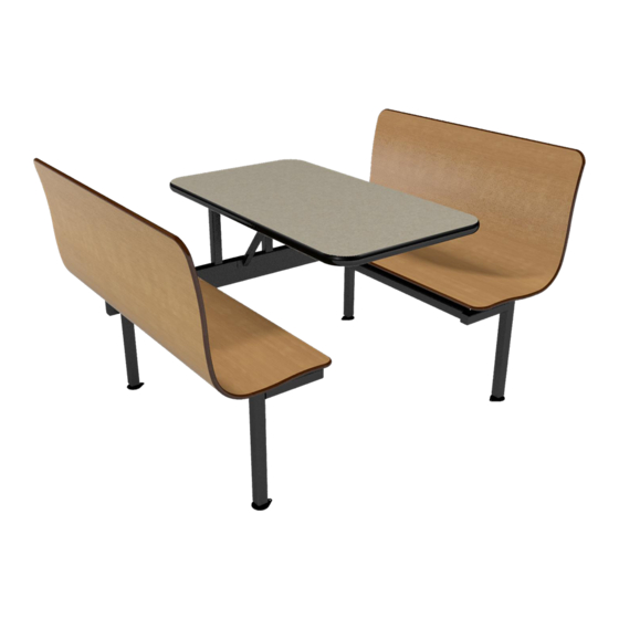
- Page 9 Contour Page 8 of 9 Assembly Step 8: Care. a. Clean furniture and protect unit un l ready for use. Wall Style Adjustable Frame Contour Booth ...
Need help?
Do you have a question about the Plymold Contour Wall Style Adjustable and is the answer not in the manual?
Questions and answers