Table of Contents
Advertisement
Quick Links
Mercury+ ST1 Base Board
Purpose
The purpose of this document is to present the characteristics of Mercury+ ST1 base board to the user, and
to provide the user with a comprehensive guide to understanding and using the Mercury+ ST1 base board.
Summary
This document first gives an overview of the Mercury+ ST1 base board followed by a detailed description of
its features and configuration options. In addition, references to other useful documents are included.
Product Information
Product
Document Information
Reference / Version / Date
Approval Information
Written by
Verified by
Approved by
User Manual
Code
ME-ST1
Reference
D-0000-456-001
Name
HMEY, NALI
HMEY
DIUN
Enclustra GmbH – Räffelstrasse 28 – CH-8045 Zürich – Switzerland
Name
Mercury+ ST1 Base Board
Version
02
Position
Design Engineer
Design Expert
Manager, BU SP
Phone +41 43 343 39 43 – www.enclustra.com
Date
23.07.2020
Date
07.05.2020
11.05.2020
23.07.2020
Advertisement
Chapters
Table of Contents

Related Manuals for Enclustra Mercury+ ST1

Summary of Contents for Enclustra Mercury+ ST1
- Page 1 User Manual Purpose The purpose of this document is to present the characteristics of Mercury+ ST1 base board to the user, and to provide the user with a comprehensive guide to understanding and using the Mercury+ ST1 base board. Summary This document first gives an overview of the Mercury+ ST1 base board followed by a detailed description of its features and configuration options.
- Page 2 Unauthorized duplication of this document, in whole or in part, by any means is prohibited without the prior written permission of Enclustra GmbH, Switzerland. Although Enclustra GmbH believes that the information included in this publication is correct as of the date of publication, Enclustra GmbH reserves the right to make changes at any time without notice.
-
Page 3: Table Of Contents
Table of Contents Overview General ........... 1.1.1 Introduction . - Page 4 Power Sequencing ..........27 Power Enable/Power Good .
-
Page 5: Overview
1.1.4 Disposal and WEEE The Mercury+ ST1 base board must be properly disposed of at the end of its life. If a battery is installed on the board, it must also be properly disposed of. The Waste Electrical and Electronic Equipment (WEEE) Directive (2002/96/EC) is not applicable for the Mer- cury+ ST1 base board. -
Page 6: Electrostatic Discharge
1.1.7 Electromagnetic Compatibility The Mercury+ ST1 base board is a Class A product (as defined in IEC 61000-3-2 standard) and is not in- tended for use in domestic environments. The product may cause electromagnetic interference, for which appropriate measures must be taken. -
Page 7: Accessories
Accessories Mercury FPGA or SoC module 12 V DC/1.5 A power supply USB 2.0 A to micro-B USB cable D-0000-456-001 7 / 48 Version 02, 23.07.2020... -
Page 8: Getting Started
2 Getting Started This section contains essential information on using the Mercury+ ST1 base board. Before first use of the Mercury+ ST1 base board with a Mercury or Mercury+ module, the following steps must be followed: Mount the module on the module slot on the base board, with the power switched off. -
Page 9: Board Description
3 Board Description Block Diagram The Mercury+ ST1 base board can be used in combination with any Mercury module. Depending on the equipped module some features may not be available. The block diagram of the Mercury+ ST1 base board is shown in Figure 1. -
Page 10: Features
Features Table 1 describes the features available on the Mercury+ ST1 base board. Feature Description Form factor 100 mm System features Built-in Xilinx JTAG (via USB connection) Low-jitter clock generator Programmable user oscillator (optional) Memory microSD card holder Connectors USB 3.0 connectors (host & device) RJ45 Gigabit Ethernet connectors Micro USB (FTDI USB 2.0 High-Speed device controller) -
Page 11: Article Numbers And Article Codes
The correspondence between article number and article code is shown in Table 3. The article code repre- sents the product code, followed by the revision; the R suffix and number represent the revision number. The revision changes and product known issues are described in the Mercury+ ST1 Base Board Known Issues and Changes document [5]. -
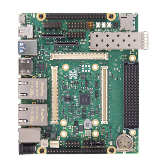
Page 12: Top And Bottom Views
Top and Bottom Views 3.5.1 Top View Figure 3: Board Top View D-0000-456-001 12 / 48 Version 02, 23.07.2020... -
Page 13: Bottom View
3.5.2 Bottom View Figure 4: Board Bottom View Please note that depending on the hardware revision and configuration, the base board may look slightly different than shown in this document. D-0000-456-001 13 / 48 Version 02, 23.07.2020... -
Page 14: Top And Bottom Assembly Drawings
Top and Bottom Assembly Drawings 3.6.1 Top Assembly Drawing C304 Figure 5: Board Top Assembly Drawing D-0000-456-001 14 / 48 Version 02, 23.07.2020... -
Page 15: Bottom Assembly Drawing
3.6.2 Bottom Assembly Drawing Figure 6: Board Bottom Assembly Drawing Please note that depending on the hardware revision and configuration, the base board may look slightly different than shown in this document. D-0000-456-001 15 / 48 Version 02, 23.07.2020... -
Page 16: Board Dimensions
Board Dimensions Figure 7: Board Dimensions D-0000-456-001 16 / 48 Version 02, 23.07.2020... -
Page 17: Mechanical Data
Mechanical Data Table 4 describes the mechanical characteristics of the Mercury+ ST1 base board. A 3D model (PDF) and a STEP 3D model are available [6], [7]. Symbol Value Size 100 mm Component height top 11.3 mm Component height bottom... -
Page 18: Connectors Description
Table 7: J1701 - External Power Connector Type 12 V Internal Power (J1700) The Mercury+ ST1 base board base board can alternatively be powered through the internal power input connector J1700. The 12 V DC power source connected to J1700 must be filtered by external power circuitry. -
Page 19: Fan Connector (J1601)
A detailed pinout of the Mercury module connector can be found in the Mercury Master Pinout [9] and in the Mercury+ ST1 Base Board User Schematics [4]. Warning! Only Enclustra Mercury FPGA/SoC modules should be inserted into the Mercury+ ST1 base board. Warning! The VCC_IO pins are directly connected to the FPGA/SoC device. Apply only compliant voltages to the VCC_IO pins;... -
Page 20: Usb 3.0 Host Connector (J602)
4.10 SFP+ Connector (J1100) The Mercury+ ST1 base board is equipped with a SFP+ socket. The capability of the SFP+ interface depends on the connected Mercury module as well as on the plugged SFP+ module. The SFP+ connector J1100 is connected by default to the Mercury module connector C, pins C-63/65 (TX side) and C-66/68 (RX side). -
Page 21: Hdmi Connector (J1300)
4.12 HDMI Connector (J1300) The Mercury+ ST1 base board is equipped with an HDMI connector. The signals available on this connector are routed to/from the FPGA banks on the SoC/FPGA device on the Mercury module via HDMI Redriver U1300. Refer to section 6.7 for details on the HDMI interface and connectivity options. -
Page 22: Fmc Jtag Connector (J1506)
The FMC I2C interface is connected to the FPGA I2C interface (I2C_SDA/SCL_FPGA) available on module connector A. Please refer to the Mercury Master Pinout [9] and the Mercury+ ST1 Base Board User Schematics [4], for details on FMC connectivity. 4.16 FMC JTAG Connector (J1506) The FMC JTAG connector allows accessing the JTAG port of the mounted FMC. -
Page 23: Anios I/O Connector Io0/Io1 (J1501/J1505)
The Anios I/O connectors can be used for user applications: each connector provides 24 user I/Os, a dif- ferential clock connection, connectivity to the I2C bus, and power supply connections. The clock, data and I2C signals are routed to the module connector - for details, refer to the Mercury+ ST1 Base Board User Schematics [4]. -
Page 24: Battery Holder (J1600)
The I/O pins are connected directly to the FPGA/SoC device. Use only VCC_IO voltages compliant with the equipped FPGA/SoC device; any other voltage may damage the mounted Mercury FPGA/SoC module, as well as other devices on the Mercury+ ST1 base board. Warning! Do not insert a PMOD module to these connectors if the corresponding VCC_IO_[x] supply is not 3.3 V,... -
Page 25: J1502 - Fpga Jtag Connector
FPGA/SoC device as well as other devices on the module or Mercury+ ST1 base board. The JTAG connector available on the Mercury+ ST1 base board can be used in combination with Xilinx Plat- form Cable USB or Intel USB-Blaster download cable. For Xilinx JTAG connection, the flying wire adapter must be used. -
Page 26: Power
5 Power Power Input The Mercury+ ST1 base board can be powered using one of the power input sources listed below: External power connection through J1701 barrel jack connector Internal power connection through J1700 connector Power Generation Overview Table 18 describes the power supplies available on the base board. -
Page 27: Maximum Power Budget
Figure 8: Maximum Power Budget Estimation Power Sequencing The Mercury+ ST1 base board will only power up when a Mercury module is properly connected to its socket. As soon as the main voltage (VCC_MAIN) is applied, VCC_5V will start up and the mated Mercury module will drive up a 3.3 V supply (VCC_3V3_MOD). -
Page 28: Power Enable/Power Good
- please refer to the module’s user manual for details on power generation. On the Mercury+ ST1 base board the VCC_5V supply is always active and cannot be turned-off, except for when removing the 12 V power input on the board. -
Page 29: Vcc_Io Source Pins Positions - Power Pins
VCC_FMC_VIOB is a supply output from the FMC card. Only one source for each I/O voltage VCC_IO_A, VCC_IO_B or VCC_IO_C is allowed. The factory default jumper settings are 1-2, 7-8, 11-13. As a consequence of these settings, no voltage is applied to the Mercury module connector, therefore it prevents the module from booting. PWGD LED will not be lit. -
Page 30: Jumper Settings Vcc_Io_B
Warning! Use only VCC_IO_A, B and C voltages compliant with the equipped Mercury module; any other voltages may damage the equipped Mercury module, as well as other devices connected to Mercury+ ST1 base board. Figure 11 shows the pin numbering for connector J1602 and provides one configuration example. -
Page 31: Vcc_Io Jumper Positions - Pin Numbering And Configuration Example
Figure 11: VCC_IO Jumper Positions - Pin Numbering and Configuration Example D-0000-456-001 31 / 48 Version 02, 23.07.2020... -
Page 32: Board Function
Mercury module User LED Table 22: Board LEDs For details on the LED connections, refer to the Mercury+ ST1 Base Board User Schematics [4]. Buttons All buttons are active-low; their function is described in Table 23. The user buttons can be configured by the user to have various functions. For details, refer to the Mercury+ ST1 Base Board User Schematics [4]. -
Page 33: Dip Switches
DIP Switches There is a 4-bit configuration switch on the Mercury+ ST1 base board. Table 24 describe its function; the factory default is marked in bold. Warning! Please note that the DIP switches must be configured according to the connectivity requirements. The factory default configuration does not implicitly indicate a valid configuration. -
Page 34: Usb
Figure 12 presents an overview of the USB connections on the Mercury+ ST1 base board. Figure 12: USB Connections Overview Table 25 describes the connectivity options for USB on the Mercury+ ST1 base board. The default configu- ration is marked in bold. -
Page 35: Usb 2.0 Device Controller (Ftdi)
By default, the UART communication between the FTDI device and FPGA is active. The Xilinx JTAG mode can be activated using the Enclustra MCT [10] and is independent of the UART connection. The library used by the MCT is available free of charge; it allows users to integrate module enumeration, FPGA and SPI flash configuration, and I2C communication functionality in their own application. -
Page 36: I2C Communication
I2C Communication There are several I2C devices on the Mercury+ ST1 base board connected to two separate I2C buses. The Mercury module and the FTDI device can be I2C masters on the main I2C bus. An overview of the I2C structure is given in Table 27 and Figure 13. -
Page 37: I2C Devices
The I2C_SCL_FPGA and I2C_SDA_FPGA signals are connected with 0 resistor jumpers to HDMI and FMC connectors. The programmable oscillator Si570 is not equipped on the Mercury+ ST1 base board by default, therefore the address space 0x2A is not automatically occupied. D-0000-456-001 37 / 48 Version 02, 23.07.2020... -
Page 38: Hdmi
Table 27: I2C Structure HDMI The Mercury+ ST1 base board supports HDMI 1.4b and 2.0b output signals. The display data channel (DDC) for audio and video format recognition is wired to the I2C FPGA bus (pins A-55/57). The standard I2C bus (A-111/113) is used for the redriver configuration. -
Page 39: Displayport
Lanes 0 and 1 are mapped directly to the transmitter side of the MGTs, while lane 2 and 3 are mapped to MGT receivers. This allows a full duplex link between two individual Mercury+ ST1 base boards by connecting a mini DisplayPort cable, for example for debugging or performance evaluation purposes. -
Page 40: Mipi Csi/Dsi Interface With Zynq Ultrascale+ Modules
Board Reference / Pins CSI mapping DSI mapping J1001 / 7,8 Clock Data Lane 0 J1001 / 10,11 Data Lane 1 Clock J1001 / 13,14 Data Lane 0 Data Lane 1 Table 28: MIPI Connector 1 CSI / DSI Signal Mapping - Rasperry Pi Display Lane Mapping Figure 17 shows the connections for the CSI and DSI use cases. -
Page 41: Clock Architecture
6.10 Clock Architecture The Mercury+ ST1 base board provides the user with a diversity of clock configuration options. The board is equipped with a clock generator programmable via I2C having as reference a 100 MHz clock from an oscillator (Y801). Alternatively, a user oscillator (Y800) with another frequency can be used as reference - this part is not equipped by default on the board. -
Page 42: Clock Generator
Figure 18: Clock Architecture Overview 6.10.1 Clock Generator The Mercury+ ST1 base board features a clock generator circuit addressable and configurable via I2C. Type Manufacturer Si5338B-B-GMR Silicon Labs Table 32: Clock Generator Type The clock generator has to be configured at power-up via I2C by the Mercury module or by another I2C master. -
Page 43: Operating Conditions
7 Operating Conditions Absolute Maximum Ratings Table 33 indicates the absolute maximum ratings for Mercury+ ST1 base board. Symbol Description Rating Unit VCC_MAIN_IN Supply voltage relative to GND -0.3 to 16 Refer to the Mercury VCC_IO_[x] VCC I/O input voltage relative to GND... -
Page 44: Ordering And Support
8 Ordering and Support Ordering Please use the Enclustra online request/order form for ordering or requesting information: http://www.enclustra.com/en/order/ Support Please follow the instructions on the Enclustra online support site: http://www.enclustra.com/en/support/ D-0000-456-001 44 / 48 Version 02, 23.07.2020... - Page 45 List of Figures Hardware Block Diagram ........Product Label .
- Page 46 Recommended Operating Conditions ....... . . 43 USB Use Case Scenario ......... . 48 D-0000-456-001 46 / 48 Version 02, 23.07.2020...
- Page 47 [1] Enclustra General Business Conditions http://www.enclustra.com/en/products/gbc/ [2] Enclustra FPGA Manager IP Solution http://www.enclustra.com/en/products/fpga-manager/ [3] Mercury+ ST1 Base Board IO Net Length Excel Sheet Ask Enclustra for details [4] Mercury+ ST1 Base Board User Schematics Ask Enclustra for details [5] Mercury+ ST1 Base Board Known Issues and Changes...
-
Page 48: A Appendix
A Appendix Module USB-B USB-A PS MGT2 SS PS MGT3 SS FX3 SS Scenario MODE1 MODE0 HS1_OE# USB0 USB1 e.g. DIP Switch DIP Switch Logic seen from seen from seen from seen from seen from seen from seen from connector connector module module...
Need help?
Do you have a question about the Mercury+ ST1 and is the answer not in the manual?
Questions and answers