Advertisement
Quick Links
J. HAIB LE Dual WAS P Filter ( Euro)
J
H A I B L E D U A L W A S P V C F
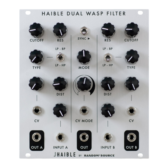
Jürgen Haible's WASP Filter adaption of the famous CMOS VCF introduced some unique features, in particular
a distortion stage. The R*S version takes this a step further by turning it into a dual version with a dynamic link
that allows to combine the filters in series or parallel or anything in between - even voltage controlled. Also, each
side can blend from lowpass to highpass or bandpass (yes, the notch is in there, too!) creating infinite filterbank
combinations. A Sync switch has been added to be able to control both side's cutoff frequency with from the left
side. The unique distortion can be configured to PRE or POST for each side.
The R*S kit is the only authorised adaption of the Haible WASP VCF for Eurorack.
Features
•
2 Identical Haible WASP filters including distortion.
•
Blend from Lowpass to Highpass or Bandpass.
•
Distortion can be configured to be PRE or POST.
•
MODE blends from serial to parallel setup - even CV controlled.
•
SYNC: control Cutoff of both filters at the same time.
•
Infinite options from 4-pole VCF to Stereo filter.
•
Massive drone machineComplex oscillator when patched to self-oscillate.
•
No wiring needed.
RANDOM*SOURCE
RANDOMSOURCE.NET
( E u r o )
1
Advertisement

Related Manuals for Random*Source JHAIBLE Dual WASP Filter


Summary of Contents for Random*Source JHAIBLE Dual WASP Filter
- Page 1 RANDOM*SOURCE J. HAIB LE Dual WAS P Filter ( Euro) H A I B L E D U A L W A S P V C F ( E u r o ) Jürgen Haible’s WASP Filter adaption of the famous CMOS VCF introduced some unique features, in particular a distortion stage.
- Page 2 RANDOM*SOURCE J. HAIB LE Dual WAS P Filter ( Euro) Filter sections • Audio input with level pot • CV inputs for Cutoff with attenuators • Resonance knob Type knob: blend output between LOWPASS and HIGHPASS or LOWPASS and BAND- • PASS (set Type destination with the Type-Switch) Distortion knob (Distortion can be configured to PRE filter or POST filter using jumpers) • Control section (Center) • SYNC switch: when activated, Cutoff and CV from the left side control the right side, too. This opens up amazing possibilites: use both sides separately (turn MODE to parallel) as a stereo filter or set MODE to serial for a 4-pole (24db) WASP filter. • MODE knob: blend from SERIAL to PARALLEL. • MODE CV input: MODE can be voltage controlled(!) • MODE CV knob: attenuverter to control how the CV affects the MODE •...
- Page 3 RANDOM*SOURCE J. H AIB L E Dua l WA SP Filter ( Euro) The R*S kit consists of a main pcb and a matching panel pcb which serves as an interface to the front panel. Bot pcbs version 1.00 are through-hole (TH) with only very few optional SMT parts (BCM857 on the main pcb...
- Page 4 RANDOM*SOURCE J. HAIB LE Dual WAS P Filter ( Euro) • There are 2 pairs of (optional) trimmers to optimize the MODE performance: “TRIM X” and “TRIM Y” control CV Rejection. These can be calibrated by ear (or scope). See details below. “BIAS” trimmers can be used to eliminate output offset, for this you need a good scope (a good DMM might work, too). This is really for the perfectionists - see calibration info below -, so if you don’t have a scope, it’s probably best not to bother: install RGX, RGY and a link from pin 1 to 2 (center) or 3. • Be careful: 2 of the op-amps (left and right) are SINGLE! The ones in the center row are DUAL. Do not confuse SINGLE and DUAL op-amps up or they will burn! • There’s a dual op-amp (in SMT) on the panel pcb: without this, turning the CV attenuator (without CV going in) will affect the Cutoff frequency. Install the op-amp to avoid this (but omit the resistors marked RLX!) • Recommenden: use OPA2134 (instead of TL072) for all dual op-amps and OPA134 for the single ones.
-
Page 5: Bill Of Materials
RANDOM*SOURCE J. H AIB L E Dua l WA SP Filter ( Euro) Bill of Materials Trimmers 2 100k CV_REJECT1, CV_REJECT2 Trimpots (Bourns 3362P or Vishay T73YP...) or anything that fits - Singe turn should do Optional - trimmers to adjust CV rejection for the MODE circuitry, RTX and RTY are needed if installing trimmers! 2 100k BIAS1, BIAS2 Trimpots (Bourns 3362P or Vishay T73YP...) Optional - use trimmer and lower RGX, RGY or use link and keep RGX, RGY - see text! Resistors (1%) 2 BEAD F1, F2 Ferrit Bead 2 RLX R12, R13 Install links / 0R (only) if NOT using IC10! - Page 6 RANDOM*SOURCE J. H AIB L E Dua l WA SP Filter ( Euro) 4 1n C2, C3, C11, C12 Styroflex (or C0G/NPO) 19 100n C5, C6, C14, C15, CP3, CP4, Bypass Caps - Film recommended, X7R is OK CP5, CP6, CP7, CP8, CP9, CP10, CP11, CP12, CP13, CP14, CP15, CP16, CP17 2 10n or 100n C27, C28 Bypass caps on panel pcb - SMT or TH 5 220n C1, C9, C10, C18, C19 Film 5% (e.g. WIMA) or C0G 2 10uF CP1, CP2 Electrolytic 8 10uF NP C20, C21, C22, C23, C24, C25, Nichicon Muse NP Mouser: 647-UES1V100MEM...
-
Page 7: Power Connector
RANDOM*SOURCE J. HAIB LE Dual WAS P Filter ( Euro) Power Connector The module is designed to be powered using a standard Eurorack 10-pin DIP header (pinout +12V / GND / GND / GND / -12V with the red stripe on the cable indicating the -12V side). - Page 8 RANDOM*SOURCE J. H AIB L E Dua l WA SP Filter ( Euro) Once everything is nicely in place, solder the pots, jacks und switch onto the component pcb (while the front panel is attached). Build the main board with all through-hole-parts required, beginning with the resistors, caps etc.
-
Page 9: Power Consumption
RANDOM*SOURCE J. H AIB L E Dua l WA SP Filter ( Euro) Some Troubleshooting Tips • First make sure both sides work correctly, i.e. ignore the middle section completely, feed a signal into each side and listen to OUT A / OUT B. If only one side does not work: compare both sides, they are iden- tical, so a build issue is likely on the side not working. If both sides do not work, it seems to be a system- atic problem, check power, values, op-amp orientations etc.
Need help?
Do you have a question about the JHAIBLE Dual WASP Filter and is the answer not in the manual?
Questions and answers