
Subscribe to Our Youtube Channel
Related Manuals for Cytron Technologies SK40C

Summary of Contents for Cytron Technologies SK40C
- Page 1 ROBOT . HEAD to TOE P roduct User’s Manual – S K40C Rev2.0 SK40C 40 PINS PIC START-UP KIT User's Manual V2.0 JUNE 2015 Created by Cytron Technologies Sdn. Bhd. – All Rights Reserved...
-
Page 2: Table Of Contents
ROBOT . HEAD to TOE P roduct User’s Manual – S K40C Rev2.0 INDEX Introduction/Overview Packing List Product Specification And Limitations Dimension Board Layout Hardware Software Getting Started Warranty Created by Cytron Technologies Sdn. Bhd. – All Rights Reserved... -
Page 3: Introduction/Overview
This kit comes W ITHOUT PIC microcontroller to provide the freedom for user to choose PIC type. This document explains the method to use SK40C. Created by Cytron Technologies Sdn. Bhd. – All Rights Reserved... -
Page 4: Packing List
s ales@cytron.com.my immediately. 1. 1 x SK40C board with all components shown soldered 2. 1 x 16-way Header pin for LCD Display. 3. 1 x 20MHz Crystal 4. PIC MCU – N ot included , please purchase separately from ... -
Page 5: Product Specification And Limitations
P roduct User’s Manual – S K40C Rev2.0 3. PRODUCT SPECIFICATION AND LIMITATIONS SK40C is designed to offer starting up platform for development, the specification of PIC MCU used should be referred. Absolute Maximum Rating Symbol Parameter Unit... -
Page 6: Dimension
ROBOT . HEAD to TOE P roduct User’s Manual – S K40C Rev2.0 4. DIMENSION Created by Cytron Technologies Sdn. Bhd. – All Rights Reserved... -
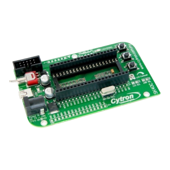
Page 7: Board Layout
ROBOT . HEAD to TOE P roduct User’s Manual – S K40C Rev2.0 5. BOARD LAYOUT Top View Bottom View Created by Cytron Technologies Sdn. Bhd. – All Rights Reserved... - Page 8 ICSP pin to load program besides using UIC00B. 3. UART connector Reserved for UART communication. Tx and Rx pin of SK40C are connect to RC6 and RC7 respectively. Ensure PIC Microcontroller chosen has the correct UART pin (RC6 and RC7).
- Page 9 (usually personal computer or laptop). This function is only valid for certain model of PIC microcontroller. Please refer to USB interface section. The USB connection also provides 5V from USB port (computer or laptop or 5V charger) to the SK40C. The power LED will light ON when the USB cable is connected.
- Page 10 Backlight negative input Connect to JP8 Table below shows pin connection for Turn pin of crystal oscillator Name Pin Function Connection OSC2 Crystal oscillator Turn pin (JP7) OSC1 Crystal oscillator Turn pin(JP7) Created by Cytron Technologies Sdn. Bhd. – All Rights Reserved...
- Page 11 Name Pin Function Connection Transmit Data TX pin of SK40C UART Received Data RC pin of SK40C UART * For detailed connection, please refer to S K40C Rev2.0 Schematic. Created by Cytron Technologies Sdn. Bhd. – All Rights Reserved...
-
Page 12: Hardware
After plug in 40-pin PIC MCU (make sure the orientation is correct) of your choice, SK40C should be powered by D C adaptor . Now, the hex code is ready to be loaded to SK40C. For the usage of UIC00A/B, please refer to UIC00A/B User’s Manual. - Page 13 ● To use PICkit 3 as programmer, user has to solder 1x6 way right angle header pin to JP10. ● Connect PICkit 3 at JP10. Ensure the arrow on SK40C is same with arrow at PICkit 3. Created by Cytron Technologies Sdn. Bhd. – All Rights Reserved...
- Page 14 ● Connect the components that needed onto the I/O port. ● Plug the I/O pins of the Start-up Kit onto a breadboard. Then, extend the I/O port to Input Output device using jumper wires. Created by Cytron Technologies Sdn. Bhd. – All Rights Reserved...
- Page 15 P roduct User’s Manual – S K40C Rev2.0 ● Plug the I/O pins of the Start-up Kit onto a donut board. Solder the pins onto the board to access the I/O. Created by Cytron Technologies Sdn. Bhd. – All Rights Reserved...
- Page 16 ● Solder 16-way h eader pin to the LCD. ● Solder LCD on to SK40C as shown. To enable LCD backlight (optional), solder JP8 to connect the LCD B/L. Created by Cytron Technologies Sdn. Bhd. – All Rights Reserved...
- Page 17 JP8 and use mini jumper to connect LCD B/L. Header pin and mini jumper is n ot included in SK40C packing list. Users need to buy separately. Created by Cytron Technologies Sdn. Bhd. – All Rights Reserved...
- Page 18 ROBOT . HEAD to TOE P roduct User’s Manual – S K40C Rev2.0 ● Potentiometer is used to adjust the contrast of LCD. Turn left or right to adjust the contrast. Created by Cytron Technologies Sdn. Bhd. – All Rights Reserved...
- Page 19 S K40C Rev2.0 6.4 UART Interface UART port is provided on SK40C for communication to microcontroller or computer. Users need to solder 2510-04 connector to utilize the UART. 2510-04 connector is not included on SK40C packaging list. ● Solder 2510-04 connector at UART as shown.
- Page 20 S KPS . In other words, Tx pin of SK40C should be connected to Rx pin of SKPS, while Rx pin of SK40C should be connected to Tx pin of SKPS. No extra component is necessary between these connections. For details connection, please refer to sample schematic.
- Page 21 UART pins of UC00A. Tx and Rx pin of SK40C should be cross connected to Tx and Rx pin of UC00A. In other words, Tx pin of SK40C should be connected to Rx pin of UC00A, while Rx pin of SK40C should be connected to Tx pin of ...
- Page 22 RS232 in serial communication. 6.5.1 SK40C USB USB data pins (pin 23, D- and pin 24, D+) are connected to a mini-B USB port on SK40C board for USB development. So far, Microchip has only 5 USB 8-bit microcontrollers in 40-pin PDIP package such as PIC18F4450, PIC18F4455, ...
- Page 23 S K40C Rev2.0 ● Make sure your crystal frequency is 20MHz (unless you change the configuration of the MCHPFSUSB Framework) and jumper SEL USB is connected (soldering) as shown below. Created by Cytron Technologies Sdn. Bhd. – All Rights Reserved...
-
Page 24: Software
Cytron Technologies has provided the SK40C HID USB Bootloader firmware (edited form MCHPFSUSB Framework). This firmware is currently configured to work with the PIC18F4550 using the CYTRON SK40C. However, user can always use this code for other USB microcontroller after doing some project modification. Loads the appropriate hex file to PIC by using the programmer (UIC00A/B). - Page 25 . It’s not valid for USB at SK40C. 1. Open HyperTerminal. Enter a name and choose an icon for connection as picture below then click OK. 2. Select COM port Created by Cytron Technologies Sdn. Bhd. – All Rights Reserved...
- Page 26 As an example (shown in following figure), COM Port for UC00A is COM34. T he COM Port is not definitely s ame for each computer. Usually, the COM Created by Cytron Technologies Sdn. Bhd. – All Rights Reserved...
- Page 27 UC00A and plug in back. The COM port for UC00A disappears when we unplug UC00A and appear when we plug in. 7. Set the “Port Setting” as picture below. Bits per seconds must be same with SK40C Baud Rate in programming. After finish setting, click Apply and then click OK.
- Page 28 P roduct User’s Manual – S K40C Rev2.0 8. Click Properties button. ‘SK40C’ Properties will show. Choose Setting tab and click ASCII Setup. Click on E cho typed characters locally and then click OK. E cho typed characters locally i s to display what is being typed on keyboard. User may click or unclick ...
-
Page 29: Getting Started
S K40C Rev2.0 8. GETTING STARTED SK40C is ready to be plug and use. It is a hardware platform, please install the necessary driver or configure the correct setting in Window. SK40C is ready be used to start the electronics interface. - Page 30 For microcontroller to interface with SK40C, the minimum requirement will be TTL UART (Universal Asynchronous Receiver and Transmitter) and 5V supply. As for UART, a minimum of Receiver pin is required to receive command from SK40C. 1. Please refer ...
- Page 31 SW2, press and release RESET button without unplug the USB cable. 5. SK40C has secondary power supplied by USB port, so external power may not needed for USB application. LED1 and LED2 will alternate blink at the time when in boot mode.
- Page 32 Cytron website under “Useful Document” of SK40C. 7. And this window will pop out and click “Open Hex File” 8. Search “SK40C 18F_USB Sample Program” folder which user has downloaded from website. There are 3 sample programs which are LCD Display, LED Blinking and UART.
- Page 33 P roduct User’s Manual – S K40C Rev2.0 9. Select the given hex file “SK40C sample code (bootloader).hex” folder and click open. Note that the original sample hex file, “SK40C sample code (bootloader).hex” is for PIC18F4550. 10. Click “Program/Verify” to load hex file to your PIC and programming status will be shown as below.
- Page 34 12. Choose decided PIC let say PIC18F4553 then click “OK”. 13. Edit the appropriate linker file. User MUST use the given remapped linker files for the application if bootloader is used. Created by Cytron Technologies Sdn. Bhd. – All Rights Reserved...
- Page 35 P roduct User’s Manual – S K40C Rev2.0 14. Right click the linker file under Linker Script folder and remove it. 15. Right click the Linker Script folder then click “Add Files” Created by Cytron Technologies Sdn. Bhd. – All Rights Reserved...
- Page 36 17. Lastly, do not forget to change the include file before rebuild it. User is free to edit the sample program. 18. Make sure the linker file and the selected device is correct. Created by Cytron Technologies Sdn. Bhd. – All Rights Reserved...
- Page 37 PIC by using the Microchip USB HID Bootloader as mentioned from step 7 to step 10 in this section. Make sure compiler used is C18 Compiler V3.32 or above. Created by Cytron Technologies Sdn. Bhd. – All Rights Reserved...
-
Page 38: Warranty
No. 16, Jalan Industri Ringan Permatang Tinggi 2, Kawasan Industri Ringan Permatang Tinggi, 14100 Simpang Ampat, Penang, Malaysia. Tel: +604-505 1878 Fax: +604-504 0138 URL: www.cytron.com.my Email: s upport@cytron.com.my sales@cytron.com.my Created by Cytron Technologies Sdn. Bhd. – All Rights Reserved...
Need help?
Do you have a question about the SK40C and is the answer not in the manual?
Questions and answers