
Related Manuals for Cytron Technologies CIKU

Summary of Contents for Cytron Technologies CIKU
- Page 1 ROBOT . HEAD to TOE P roduct User’s Manual – C IKU CIKU User's Manual V1.0 July 2014 Created by Cytron Technologies Sdn. Bhd. – All Rights Reserved...
-
Page 2: Table Of Contents
P roduct User’s Manual – C IKU INDEX Introduction Packing List Product Specification And Limitations Dimension Board Layout Hardware Installation Getting Started Warranty Appendix A: CIKU’s Pinout Diagram Created by Cytron Technologies Sdn. Bhd. – All Rights Reserved... -
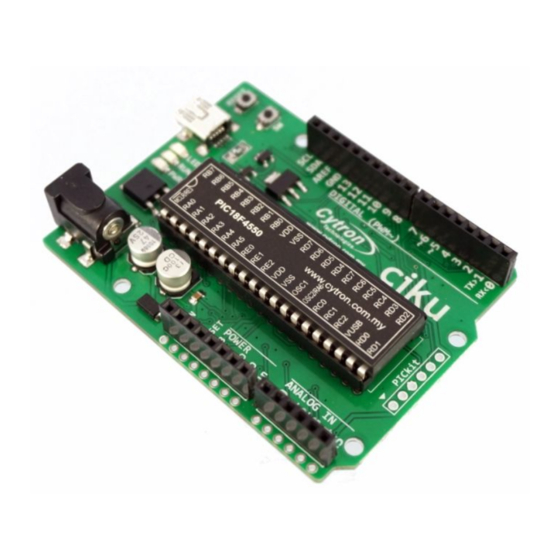
Page 3: Introduction
● Reset button and bootloader button for entering bootloader mode. ● Program with MPLAB X IDE and XC8 compiler (library provided). ● Program loading via USB HID, GUI from Microchip provided. Created by Cytron Technologies Sdn. Bhd. – All Rights Reserved... -
Page 4: Packing List
Please check the parts and components according to the packing list. If there are any parts missing, please contact us at s ales@cytron.com.my immediately. ● 1 x C IKU board Optional (not included): ● USB MiniB Cable (2.0) for program loading. Created by Cytron Technologies Sdn. Bhd. – All Rights Reserved... -
Page 5: Product Specification And Limitations
Input Voltage via Adapter (Limits) I ( from on-board 5V Voltage regulator)* M AX (5V) I ( from on-board 3.3V Voltage regulator) M AX (3.3V) * With Vin at 12V Created by Cytron Technologies Sdn. Bhd. – All Rights Reserved... -
Page 6: Dimension
ROBOT . HEAD to TOE P roduct User’s Manual – C IKU 4. DIMENSION *Note: For more details on the dimension, please refer to Eagle PCB files. Created by Cytron Technologies Sdn. Bhd. – All Rights Reserved... -
Page 7: Board Layout
5. BOARD LAYOUT Label Function Adapter socket (2.1mm) Power indicator LED Run LED Programmable LED (connected to Pin 13, active high) Mini USB B type (female) Reset button Bootloader button Created by Cytron Technologies Sdn. Bhd. – All Rights Reserved... - Page 8 Power LED will light ON once the board is powered. Run LED Run LED will blink if CIKU in bootloader mode, and turn ON if in user mode. Programmable LED Programmable LED is active HIGH and it is connected to pin 13.
-
Page 9: Hardware Installation
(12V adapter and USB cable) it will automatically choose power from adapter. ● CIKU is being powered using 12V power adapter ● Besides using 12V power adapter, CIKU also can be power up using USB cable Created by Cytron Technologies Sdn. Bhd. – All Rights Reserved... - Page 10 12V Power adapter and USB cable, it will automatically choose power from power adapter. 6.2 Downloading bootloader firmware PICkit port is reserved for user to load bootloader into CIKU. Users need to solder 1 x6 Right angle header pin...
- Page 11 , the alternative way to load bootloader is using U IC-A UIC00B 6.3 Interface CIKU ● is compatible with arduino shield. Below are examples shown CIKU S HIELD-LCD and S HIELD-PROTO2 is stacking onto CIKU. Created by Cytron Technologies Sdn. Bhd. – All Rights Reserved...
- Page 12 ROBOT . HEAD to TOE P roduct User’s Manual – C IKU ● This is example of wireless remote mobile robot that uses C IKU SHIELD-2AMOTOR and S HIELD-XBEE Created by Cytron Technologies Sdn. Bhd. – All Rights Reserved...
- Page 13 C IKU ● CIKU also can be stacked onto donut board. Users need to solder header pins at left and right side to stack CIKU onto d onut board Created by Cytron Technologies Sdn. Bhd. – All Rights Reserved...
-
Page 14: Getting Started
For your information, CIKU bootloader doesn’t need any driver to be installed since it is recognized as HID (Human Interface Devices). *When CIKU enter bootloader mode, PC will recognize CIKU as U SB Input Device . In software part, CIKU is designed to compatible with MPLAB X IDE (... - Page 15 * C IKU.X represent the CIKU Arduino library that you have downloaded . CIKU.X project files divided into 3 categories which are c ores , l ibraries , and u ser . You can write the Arduino coding style under S ource Files -> user -> template.c . The picture above shows LED blinking example.
- Page 16 To enter the bootloader mode, look at the sequence below. Sequence SW button Reset button Pressed (Hold) Released Pressed (Hold) Pressed Pressed (Hold) Released Released Released ● Run LED will blink when enter the bootloader mode. Created by Cytron Technologies Sdn. Bhd. – All Rights Reserved...
- Page 17 C IKU ● The Bootloader GUI will automatically detect there is device attached. Open your hex file, F ile -> Import Firmware Image -> CIKU.X.production.hex . If successful, it will display “Opened: CIKU.X.production.hex” under “Device Ready (0.003s)”. * P ath to hex file: C IKU.X\dist\default\production\ ...
- Page 18 ● Click on E rase/Program/Verify Device icon (middle icon) to upload the hex file into CIKU board. ● Click R eset Device icon (right icon) to start the user program on CIKU board. LED will blink with 100ms delay. Created by Cytron Technologies Sdn. Bhd. – All Rights Reserved...
-
Page 19: Warranty
No. 16, Jalan Industri Ringan Permatang Tinggi 2, Kawasan Industri Ringan Permatang Tinggi, 14100 Simpang Ampat, Penang, Malaysia. Tel: +604 - 504 1878 Fax: +604 - 504 0138 URL: www.cytron.com.my Email: s upport@cytron.com.my sales@cytron.com.my Created by Cytron Technologies Sdn. Bhd. – All Rights Reserved... - Page 20 ROBOT . HEAD to TOE P roduct User’s Manual – C IKU Appendix A: Created by Cytron Technologies Sdn. Bhd. – All Rights Reserved...
Need help?
Do you have a question about the CIKU and is the answer not in the manual?
Questions and answers