
Summary of Contents for Saia PCD2.H110
- Page 1 PCD2.H110 SAIA Universal counting and measuring module Process Control Devices English edition 26/755 E2...
- Page 2 0662 88 49 10, Fax 0662 88 49 10 11 02 456 06 20, Fax 02 460 50 44 Italy SAIA-Burgess Electronics S.r.l. Hungary SAIA-Burgess Electronics Automation Kft. Via Cadamosto 3 Liget utca 1. I-20094 Corsico MI H-2040 Budaörs 02 48 69 21, Fax 02 48 60 06 92...
- Page 3 ® SAIA Process Control Devices Universal counting and measuring module PCD2.H110 SAIA-Burgess Electronics Ltd. 1999 all rights reserved Edition 26/755 E2 - 04.99 Subject to technical changes SAIA-Burgess Electronics Ltd.
- Page 4 Updates Manual : PCD2.H110 - Universal counting and measuring module - Edition E2 Date Chapter Page Description SAIA-Burgess Electronics Ltd.
-
Page 5: Table Of Contents
The IL package (Installation of the FBs) 6.1.2 The individual FBs Programming in FUPLA with FBoxes Programming in GRAFTEC with FBoxes Error handling and diagnostics Definition errors checked by the assembler Error handling in run SAIA-Burgess Electronics Ltd. 26/755 E2 Page 1 (2H1-00-E.DOC) - Page 6 Table of contents PCD2.H110 Page PCD2.H110 for counting and motion control tasks Block diagram of counter Description of counter Configuration of inputs 'EnableC', 'CCO', 'A', 'B' and the count mode 8.3.1 Configuration of the 'EnableC' input 8.3.2 Configuration of the 'CCO' output 8.3.3...
- Page 7 StartCt Start counter A-12 StartMs Start measure A-13 StopMs Stop measure A-14 RdIdent Read module identification A-15 Appendix B: Summary of all software elements for programming in FUPLA (FBoxes) in preparation SAIA-Burgess Electronics Ltd. 26/755 E2 Page 3 (2H1-00-E.DOC)
- Page 8 Table of contents PCD2.H110 Notes SAIA-Burgess Electronics Ltd. Page 4 26/755 E2 (2H1-00-E.DOC)
- Page 9 Please note: A number of detailed manuals are available to aid installation and operation of the SAIA PCD. These are for use by technically qualified staff, who may also have successfully completed one of our workshops. To obtain the best performance from your SAIA PCD, closely follow the guidelines for assembly, wiring, programming and commissioning given in these manuals.
- Page 10 PCD, such as the watchdog, exception organization blocks (XOB) and test or diagnostic instructions. If all these points are taken into consideration, the SAIA PCD will provide you with a modern, safe programmable controller to control, regulate and monitor your installation with reliability for many years.
-
Page 11: Introduction
1. Introduction 1.1 General The standard equipment of SAIA PCD process control devices already offers 1600 counting registers of 31 bits, although they can only capture frequencies up to approx. 20 Hz. Via the interrupt inputs, 1 kHz can be achieved and, with the ..H100 counting module, up to 20 kHz are possible. -
Page 12: Function And Application
µ 1 MHz (n 1 s) ON OFF COUNTER IN-A START 16 BITS LOGIC ENABLE TACHOMETER ENABLE LATCH REGISTER Block diagram for special OEM versions PROM WITH SPECIAL APPLICATION LOGIC FPGA SAIA-Burgess Electronics Ltd. Page 1-2 26/755 E2 (2H1-10-E.DOC) -
Page 13: Main Characteristics
PCD2.H110 Introduction 1.3 Main characteristics • Up to 16 PCD2.H110 modules in parallel operation can be inserted in one PCD2, or up to 4 in one PCD1. • Counting and measuring functions can be utilized simultaneously in the same module. -
Page 14: Typical Areas Of Application
• Automatic handling- and assembly machines • Pick and place functions • Palletising equipment • Automatic angle control, e.g. of cameras, headlamps, aerials, etc. • Motion control of static axes (set-up) SAIA-Burgess Electronics Ltd. Page 1-4 26/755 E2 (2H1-10-E.DOC) -
Page 15: Programming
- RdMsImp Read measure in impulsion - RdMsUnit Read measure in unit (Hz or ms) - StartCt Start counter - StartMs Start measure - StopMs Stop measure - RdIdent Read module identification SAIA-Burgess Electronics Ltd. 26/755 E2 Page 1-5 (2H1-10-E.DOC) - Page 16 Introduction PCD2.H110 Notes SAIA-Burgess Electronics Ltd. Page 1-6 26/755 E2 (2H1-10-E.DOC)
-
Page 17: Technical Data
10% Operating conditions Ambient temperature operation: 0 ... +50°C without forced ventilation storage: -20 ... +85°C Interference immunity CE mark according to EN 50081-1 and EN 50082-2 SAIA-Burgess Electronics Ltd. 26/755 E2 Page 2-1 (2H1-20-E.DOC) - Page 18 LED 5: Status of "TCO" output Programming Based on PCD user program (PG4) and pre-programmed functional blocks. Ordering details PCD2.H110 Universal counting and measuring module PCD9.H11E Software library with function blocks SAIA-Burgess Electronics Ltd. Page 2-2 26/755 E2 (2H1-20-E.DOC)
-
Page 19: Electrical Specification
2 A for outputs not protected against wrong polarity! Digital inputs 4 digital inputs (E0 ... E3) (see chapter 2.1) Digital outputs 2 digital outputs (A0 and A1) (see chapter 2.1) SAIA-Burgess Electronics Ltd. 26/755 E2 Page 2-3 (2H1-20-E.DOC) -
Page 20: Function Specific Data
Counting range 0 ... 16 777 215 (24 bit) Counting frequency up to 100 kHz Data protection All data in this module is volatile (non-volatile registers in the PCD can be used) SAIA-Burgess Electronics Ltd. Page 2-4 26/755 E2 (2H1-20-E.DOC) -
Page 21: Presentation
E3 E2 E1 E0 Block diagram User PROM Oscillator Input "A" Input "B" FPGA EnableC (Field Programmable EnableM Gate Array) Input filter and adjustment 24V to 5V Output amplifier 5 .. 32 VDC (Uext) SAIA-Burgess Electronics Ltd. 26/755 E2 Page 3-1 (2H1-30-E.DOC) - Page 22 Presentation PCD2.H110 Notes SAIA-Burgess Electronics Ltd. Page 3-2 26/755 E2 (2H1-30-E.DOC)
-
Page 23: Terminals, Cable And Meaning Of The Led's
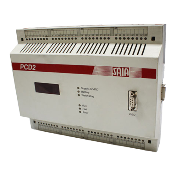
Total Terminal 4 = A0 : Output "CCO" for counter Terminal 5 = A1 : Output "TCO" for measuring functions Supply: Terminal 8 = + 24 VDC Terminal 9 = – SAIA-Burgess Electronics Ltd. 26/755 E2 Page 4-1 (2H1-40-E.DOC) - Page 24 Status of input "A" LED 1: Status of input "B" LED 2: Status of input "EnableC" LED 3: Status of input "EnableM" LED 4: Status of outputs "CCO" LED 5: Status of output "TCO" SAIA-Burgess Electronics Ltd. Page 4-2 26/755 E2 (2H1-40-E.DOC)
-
Page 25: Brief Introduction
L -> disabled H -> enabled "EnableC" L -> down H -> up "B" "A" Minimum arrangement to operate a PCD2.H110 as up/down counter. The individual elements are: PCD2 (or PCD1) equipped with at least 1 PCD2.H110 (1 PCD2.F510/530) (1 PCD2.E110) (1 PCD2.A400) -
Page 26: Getting Started With Programming In Il
The FBs (IL for PG4) are located on the diskette PCD9.H11E. To install the FBs on the PC follow the indications on the README.TXT on this diskette. The number of modules (1) and the address of the PCD2.H110 module (64) is to indicate in the file 2D2H110_B.MBA: NbrModules EQU 1 ;... - Page 27 ; ------------------------------------------ ; real user program exec ; read counter module number RdCt command: read counter register 777 ; display on display module $endgroup ecob SAIA-Burgess Electronics Ltd. 26/755 E2 Page 5-3 (2H1-50-E.DOC)
- Page 28 If no display module is disposable the value of the counter in the PCD register R 777 can be viewed in the Debugger: (Display Register 777 <Space Refresh <CR>). > SAIA-Burgess Electronics Ltd. Page 5-4 26/755 E2 (2H1-50-E.DOC)
-
Page 29: Getting Started With Programming In Fupla
PCD2.H110 Brief introduction 5.2 Getting started with programming in FUPLA in preparation SAIA-Burgess Electronics Ltd. 26/755 E2 Page 5-5 (2H1-50-E.DOC) - Page 30 Brief introduction PCD2.H110 Notes SAIA-Burgess Electronics Ltd. Page 5-6 26/755 E2 (2H1-50-E.DOC)
-
Page 31: Programming
GRAFTEC, while individual steps and transitions can be edited either in IL with FBs or in FUPLA with FBoxes. User programs, however, can also be written purely in BLOCTEC or FUPLA. SAIA-Burgess Electronics Ltd. 26/755 E2 Page 6-1 (2H1-60-E.DOC) -
Page 32: Programming In Il With Fbs
• Readme : contains general information The package is provided for the SAIA PG4 from version V2.0.70. For all other versions of PG4 consult the 'Readme' file. (The package also contains FBs for use with the older PG3, see 'Readme'). - Page 33 ;Base address of module 16 $endgroup The number of PCD2.H110 modules must be specified and the hardware base addresses of PCD2.H110 modules used should then be entered. Since the '.mba' file does not appear in Project Manager’s file list, a text editor (e.g.
- Page 34 "$endgroup" comes at the end of the last transition (TR). If everything has been correctly installed, the user program edited and all parameters defined, the program can be processed and downloaded to the PCD with the 'Project' - 'Build' command. SAIA-Burgess Electronics Ltd. Page 6-4 26/755 E2 (2H1-60-E.DOC)
-
Page 35: The Individual Fbs
Three parameters must always be defined, even if only two are required for a function. The third parameter can be defined as 'rNotUsed' or as any register. A list of all command follows on the next page. SAIA-Burgess Electronics Ltd. 26/755 E2 Page 6-5 (2H1-60-E.DOC) - Page 36 7: Error handling and diagnosis. resource list '_x' corresponds to the module number The effective addresses of the elements are shown in the resource list (for debug purposes). SAIA-Burgess Electronics Ltd. Page 6-6 26/755 E2 (2H1-60-E.DOC)
-
Page 37: Programming In Fupla With Fboxes
PCD2.H110 Programming 6.2 Programming in FUPLA with FBoxes in preparation SAIA-Burgess Electronics Ltd. 26/755 E2 Page 6-7 (2H1-60-E.DOC) - Page 38 Programming PCD2.H110 Notes SAIA-Burgess Electronics Ltd. Page 6-8 26/755 E2 (2H1-60-E.DOC)
-
Page 39: Programming In Graftec With Fboxes
PCD2.H110 Programming 6.3 Programming in GRAFTEC with FBoxes in preparation SAIA-Burgess Electronics Ltd. 26/755 E2 Page 6-9 (2H1-60-E.DOC) - Page 40 Programming PCD2.H110 Notes SAIA-Burgess Electronics Ltd. Page 6-10 26/755 E2 (2H1-60-E.DOC)
-
Page 41: Error Handling And Diagnostics
(generating the printout 'H110' from $group h110) • If the definition $group H110 is absent, then for each instruction and each register/flag used in the program the assembler reports: "Symbol not defined" SAIA-Burgess Electronics Ltd. 26/755 E2 Page 7-1 (2H1-70-E.DOC) -
Page 42: Error Handling In Run
'fPar_Err' can be viewed in file 'project.MAP'. This can be useful during commissioning with the debugger to locate an error : - Run until flag 'fPar_Err' = H - Display register 'rDiag' hex - Delete flag 'fPar_Err' SAIA-Burgess Electronics Ltd. Page 7-2 26/755 E2 (2H1-70-E.DOC) -
Page 43: Block Diagram Of Counter
PCD2.H110 Counting and motion control tasks 8. PCD2.H110 for counting and motion control tasks 8.1 Block diagram of counter Config (CTR2) A/B - Mode Input A UpDown Count Mode Preset Counter Input B Count StartC COUNTER UpDown 24 bit CStart... -
Page 44: Description Of Counter
The status of 'CCO' (CCO_x), 'EnableC' (CStart_x) and 'UpDown' (UpDown_x) can be read by the user program. SAIA-Burgess Electronics Ltd. Page 8-2 26/755 E2 (2H1-80-E.DOC) -
Page 45: Configuration Of Inputs 'Enablec
Init parameter 5 = 3 The 'EnableC' input is 'H'. The first negative edge (L) switches 'EnableC' on, the next switches it off again, etc. Standard Mode static/normal dynamic/normal static/inverted dynamic/inverted Enable Counter SAIA-Burgess Electronics Ltd. 26/755 E2 Page 8-3 (2H1-80-E.DOC) -
Page 46: Configuration Of The 'Cco' Output
'CCO' is repeated, without any new instructions from the user program. Mode static/inverted static/normal dynamic/inverted dynamic/normal Register Counter Set CCO Set CCO Evaluation of this short pulse is via the PCD1/2 interrupt inputs and XOB 20 or 25. SAIA-Burgess Electronics Ltd. Page 8-4 26/755 E2 (2H1-80-E.DOC) -
Page 47: Configuration Of The Inputs 'A' And 'B
Input 'B' normal Input 'B' inverted If a module is used as counter, inversion of a single input ('A' or 'B') results in the physical reversal of a drive's rotational direction. SAIA-Burgess Electronics Ltd. 26/755 E2 Page 8-5 (2H1-80-E.DOC) -
Page 48: Configuration Of Count Mode
Only the rising edge of signal A is evaluated. Signal B in quadrature (phase shifted by 90°) defines the count direction. Important: In mode 'x1' incremental shaft encoders should not be used because counting may be incorrect in some situations. SAIA-Burgess Electronics Ltd. Page 8-6 26/755 E2 (2H1-80-E.DOC) - Page 49 Input A Input B Enable Counter x+4 x+5 x-3 x-4 A mode 'x3' can also be selected (Init parameter 2 = 3), but has no practical uses and is not described here. SAIA-Burgess Electronics Ltd. 26/755 E2 Page 8-7 (2H1-80-E.DOC)
-
Page 50: Programmable Counter Functions
Instead of several pages of description, the programming principle is illustrated using an unstructured example. This is a functional program which can, for example, be used to test a PCD2.H110. Since counting tasks always have a sequential program flow: •... -
Page 51: Programming Principle
The program's name is "prinzip.src" and it is located in project "D2-H110". The file .MBA should also be copied into this project and the number of H110 modules (1) and the base address (64) should be indicated. Arrangement for the use of the PCD2.H110 as counter in the defined example. E110 PCD2.M120... - Page 52 Counting and motion control tasks PCD2.H110 ; ********************************************************* ; Basic user program for PCD2.H110 module as counter: ; prinzip.src ; ********************************************************* $include d2h110_b.equ $group h110 r 999 ; PCD register with start value for counter r 998 ; PCD register with value for compare register ;...
- Page 53 An empty scratch register can also be prepared here, e.g. R 0. The real configuration of the PCD2.H110 is done by calling the FB 'Init'. The call has 12 parameters. The meaning of these parameters is shown in the program example and in Appendix A of this manual.
- Page 54 This dynamic method should be used only be specialists, because conflicts between H110 FBs used in the COB and in XOB 20 may occur. Other (more realistic) applications are presented in the following examples. SAIA-Burgess Electronics Ltd. Page 8-12 26/755 E2 (2H1-80-E.DOC)
- Page 55 The user program is edited in GRAFTEC. Within the "D2-H110" project, the program is entitled "COUNT-01.SFC". The finished program will resemble the following: SAIA-Burgess Electronics Ltd. 26/755 E2 Page 8-13 (2H1-80-E.DOC)
- Page 56 11 not used for counter par 12 not used for counter ; 10 ;------------------------------- I 50 I 53 ; continue task ? O 51 ; start condition: input "start" = H ? ; 11 SAIA-Burgess Electronics Ltd. Page 8-14 26/755 E2 (2H1-80-E.DOC)
- Page 57 ; definition of counting task exec ; read counter module number RdCt command: read counter r 777 read value in R 777 r 777 ; display on display module ; PCD input "start" ; 51 SAIA-Burgess Electronics Ltd. 26/755 E2 Page 8-15 (2H1-80-E.DOC)
- Page 58 ; read counter module number RdCt command: read counter r 777 read value in R 777 r 777 ; display on display module ; PCD input "Start" $endgroup ; 53 SAIA-Burgess Electronics Ltd. Page 8-16 26/755 E2 (2H1-80-E.DOC)
- Page 59 The process itself is directly controlled from hardware with the CCO output. Before polling the switching condition (stl cco_1), the counter contents are read and displayed. This also applies to TR 51 and TR 53. SAIA-Burgess Electronics Ltd. 26/755 E2 Page 8-17 (2H1-80-E.DOC)
-
Page 60: Motion Control With Incremental Shaft Encoder
Outputs for electronics: Motor (note polarity) Supply for electronics: 24 VDC smoothed Arrangement and wiring of devices: O 97 Drive O 98 electronics IN-A Shaft DC motor encoder IN-B Carriage SAIA-Burgess Electronics Ltd. Page 8-18 26/755 E2 (2H1-80-E.DOC) - Page 61 Counting and motion control tasks Motion: Start "B" "C" Forward Backward "A" "D" 0 cm 10 mm 90 mm 100 mm Path 10'000 90'000 100'000 Pulses (mode x2) The GRAFTEC structure looks like this: SAIA-Burgess Electronics Ltd. 26/755 E2 Page 8-19 (2H1-80-E.DOC)
- Page 62 PCD register with compare value exec ; start counter, set CCO module number StartCt command: start counter empty register o 97 ; motor "fast" o 98 ; motor "forward" ; 12 SAIA-Burgess Electronics Ltd. Page 8-20 26/755 E2 (2H1-80-E.DOC)
- Page 63 PCD register with compare value exec ; start counters, set CCO module number StartCt command: start counter empty register o 97 ; motor "fast o 98 ; motor "backward" ; 15 SAIA-Burgess Electronics Ltd. 26/755 E2 Page 8-21 (2H1-80-E.DOC)
- Page 64 777 ; ¦ r 996 ; ¦ negative value r 777 ; ¦ next: r 777 ; display on display module ; PCD input "start" ; 51 SAIA-Burgess Electronics Ltd. Page 8-22 26/755 E2 (2H1-80-E.DOC)
- Page 65 ; Motor fast <-- pos "D" exec ; read counter module number RdCt command: read counter r 777 read value in R 777 r 777 ; disply on display module ; polling timer ; 54 SAIA-Burgess Electronics Ltd. 26/755 E2 Page 8-23 (2H1-80-E.DOC)
- Page 66 777 ; ¦ r 996 ; ¦ negative value r 777 ; ¦ next: r 777 ; display on display module ; polling timer $endgroup ; 57 SAIA-Burgess Electronics Ltd. Page 8-24 26/755 E2 (2H1-80-E.DOC)
- Page 67 However, this example is just to illustrate the principle. Section 9.1.5 shows how frequency can also be measured parallel to the motion control explained above. SAIA-Burgess Electronics Ltd. 26/755 E2 Page 8-25 (2H1-80-E.DOC)
-
Page 68: Measurement With Counting
For this purpose, the measurement pulses are carried to input "A" and the photoelectric barrier to the "Enable" input of the counting module, which already largely solves the problem. Measuring frequency Input "A" Input "Enable" Photoelectric barrier The GRAFTEC structure looks like this: SAIA-Burgess Electronics Ltd. Page 8-26 26/755 E2 (2H1-80-E.DOC) - Page 69 ; start counter module number StartCt command: start counter empty register ; 11 ;------------------------------- I 51 ; enable = H ? O 52 ; enable = L ? ; 12 SAIA-Burgess Electronics Ltd. 26/755 E2 Page 8-27 (2H1-80-E.DOC)
- Page 70 777 ; display on display module Cstart_1 ; polling 'EnableC' ; 52 ;------------------------------- I 13 ; counter -> PCD register O 11 ; set counter = 0 $endgroup ; 53 SAIA-Burgess Electronics Ltd. Page 8-28 26/755 E2 (2H1-80-E.DOC)
- Page 71 In ST 13 evaluation of the result is indicated. Each time the photoelectric barrier is released, the counter value is stored in consecutive PCD registers (from R 2000). Instead of a photoelectric barrier, a bounce-free switch could also be used. SAIA-Burgess Electronics Ltd. 26/755 E2 Page 8-29 (2H1-80-E.DOC)
- Page 72 Counting and motion control tasks PCD2.H110 Notes SAIA-Burgess Electronics Ltd. Page 8-30 26/755 E2 (2H1-80-E.DOC)
-
Page 73: Pcd2.H110 For Measuring Tasks
PCD2.H110 Measuring tasks 9. PCD2.H110 for measuring tasks 9.1 Frequency measurement 9.1.1 Block diagram Configuration (CTR1) Configuration (CTR2) Output m.w.register Counter of Input StartT 1 kHz EnableM measuring wind. EnableM EnableT Steuerung der Messung FlagT Measuring Overflow counter Input A... -
Page 74: Description Of Frequency Measurement
The length of the signal 'TCO' the latch and the reset of the counter takes 1.6 µs. Input A Measuring Meas. window Meas. counter TCO output 1.6 us 1.6 us 1.6 us SAIA-Burgess Electronics Ltd. Page 9-2 26/755 E2 (2H1-90-E.DOC) -
Page 75: Configuration Of Frequency Measurement
= 12 Configuration of output integer 0 – 3 0 = static-normal 1 = static-inverted 2 = dynamic-normal 3 = dynamic-inverted The complete table is shown in the appendix, page A-2. SAIA-Burgess Electronics Ltd. 26/755 E2 Page 9-3 (2H1-90-E.DOC) -
Page 76: Programming Principle
1s (1000 ms) is to be realized. The result is to be shown as counting units (Hz) on the display module. ; *********************************************** ; Basic user program for the PCD2.H110 module ; for frequency measurement: frequ-01.src ; *********************************************** $include d2h110_b.equ... - Page 77 A new measure can be started again with 'StartMs'. After a deactivate of 'EnableM' the result is not valid. A new measure can be started only with the command 'StartMs' SAIA-Burgess Electronics Ltd. 26/755 E2 Page 9-5...
-
Page 78: Combination Of Counting And Frequency Measuring
The project consists therefore of two programs: 'move-02.sfc' with the initialisation of the H110 and 'frequ-02' without XOB 16. The motion control sequence can be viewed online in GRAFTEC with the relevant frequency on the display module. SAIA-Burgess Electronics Ltd. Page 9-6 26/755 E2 (2H1-90-E.DOC) -
Page 79: Period Length Measurement
Block diagram Configuration (CTR1) Configuration Input A Tb register (CTR2) Time base StartT 1 MHz counter EnableT Measurement controller FlagT Measuring Overflow counter 16 Bit Output Input Latch EnableM EnableM measurement SAIA-Burgess Electronics Ltd. 26/755 E2 Page 9-7 (2H1-90-E.DOC) -
Page 80: Description Of Period Length Measurement
'A', measurement is always between pairs of pulses, after which there is a pause to restore readiness for the next measurement. Input A Measuring Clock M. counter Output TCO SAIA-Burgess Electronics Ltd. Page 9-8 26/755 E2 (2H1-90-E.DOC) -
Page 81: Configuration Of Period Length Measurement
= 12 Configuration of output integer 0 – 3 0 = static-normal 1 = static-inverted 2 = dynamic-normal 3 = dynamic-inverted The complete table is shown in the appendix, page A-2. SAIA-Burgess Electronics Ltd. 26/755 E2 Page 9-9 (2H1-90-E.DOC) - Page 82 1 second, 10000 clock signals are counted. The timebase will be 99 (see formula). ; *********************************************** ; Basic user program for the PCD2.H110 module ; for period length measurement: peri-01.src ; *********************************************** $include d2h110_b.equ...
- Page 83 A new measure can be started again with 'StartMs'. After a deactivate of 'EnableM' the result is not valid. A new measure can be started only with the command 'StartMs'. SAIA-Burgess Electronics Ltd. 26/755 E2 Page 9-11...
- Page 84 Measuring tasks PCD2.H110 Notes SAIA-Burgess Electronics Ltd. Page 9-12 26/755 E2 (2H1-90-E.DOC)
-
Page 85: Pulse Length Measurement
Block diagram Configuration (CTR1) Configuration Input A Tb register (CTR2) Time base StartT 1 MHz counter EnableT Measurement controller FlagT Measuring Overflow counter 16 Bit Output Input Latch EnableM EnableM measurement SAIA-Burgess Electronics Ltd. 26/755 E2 Page 9-13 (2H1-90-E.DOC) -
Page 86: Description Of Pulse Length Measurement
Remark: Negative or inverted pulse length measurement is achieved by setting 'Init' parameter 7 = '3'. Pos. pulse Pos. pulse Neg. pulse Input A Measuring Clock M. counter Output TCO SAIA-Burgess Electronics Ltd. Page 9-14 26/755 E2 (2H1-90-E.DOC) -
Page 87: Configuration Of Pulse Length Measurement
= 12 Configuration of output integer 0 - 3 0 = static-normal 1 = static-inverted 2 = dynamic-normal 3 = dynamic-inverted The complete table is shown in the appendix, page A-2. SAIA-Burgess Electronics Ltd. 26/755 E2 Page 9-15 (2H1-90-E.DOC) - Page 88 The configuration is to be designed so that for a measure time of 1 second, 1000 clock signals are counted. The timebase will be 999 (see formula). ; *********************************************** ; Basic user program for the PCD2.H110 module ; for pulse length measurement: imp-01.src ; *********************************************** $include d2h110_b.equ $group h110 ;...
- Page 89 A new measure can be started again with 'StartMs'. After a deactivate of 'EnableM' the result is not valid. A new measure can be started only with the command 'StartMs'. SAIA-Burgess Electronics Ltd. 26/755 E2 Page 9-17...
- Page 90 Measuring tasks PCD2.H110 Notes SAIA-Burgess Electronics Ltd. Page 9-18 26/755 E2 (2H1-90-E.DOC)
- Page 91 Processing time: 5 ms *) *) measured with PCD2.M120 Function description: This FB defines the settings of the PCD2.H110 module and reads the base address from file D2H110_B.MBA. Parameter '1' must be given as a 'K' constant, parameter '3' and '4' are PCD register addresses (absolute or symbolic) and all other parameters as integer numbers.
- Page 92 0 = static-normal configuration 1 = static-inverted 2 = dynam.-normal 3 = dynam.-inverted = 12 TCO configuration Integer 0 - 3 0 = static-normal 1 = static-inverted 2 = dynam.-normal 3 = dynam.-inverted SAIA-Burgess Electronics Ltd. Page A-2 26/755 E2 (2H1-AA-E.DOC)
- Page 93 Processing time: depending from the command Function description: This FB is used to send commands to the PCD2.H110 module. Module number (parameter 1) must be a 'K' constant (K 1…K 16). The base address is defined in file 'D2H110_B.MBA'. These FBs support up to max.
- Page 94 Summary of software elements for IL PCD2.H110 Individual instructions for PCD2.H110 (FB parameters) LdCtPres Command: Load counter preset Exec Function Block Module number LdCtPres Register with load value Index modified: Processing time: 1.5.ms Function description: This command loads the preset counter value.
- Page 95 CCO will be set according to the CCO configuration. Description of participating input/output elements: Par. Designation/Function Type Format Value Comment Module number 1 - 16 Command: LdRegPres 24 bit counter PCD reg. with load value Integer 0 - 16777215 SAIA-Burgess Electronics Ltd. 26/755 E2 Page A-5 (2H1-AA-E.DOC)
- Page 96 This command is used only if the configuration should be changed during the program run. Normally, the configuration is done on the beginning of the program in the FB 'Init' (parameter 9). SAIA-Burgess Electronics Ltd. Page A-6 26/755 E2...
- Page 97 500 Hz the measure window has to be: 2000 ms Formula: f = frequency 1000 * R t = time of measure window R= resolution In case of period or impulsion length measure, see next page: SAIA-Burgess Electronics Ltd. 26/755 E2 Page A-7 (2H1-AA-E.DOC)
- Page 98 1µs to reinitialize itself. Description of participating input/output elements: Par. Designation/Function Type Format Value Module number 1 - 16 Command: LdMsVal PCD reg. with load value integer 0 - 65535 16 bit SAIA-Burgess Electronics Ltd. Page A-8 26/755 E2 (2H1-AA-E.DOC)
- Page 99 This command reads the actual counter value. Description of participating input/output elements: Par. Designation/Function Type Format Value Com. Module number 1 - 16 Command: RdCt PCD register for result integer 0 - 16777215 24 bit SAIA-Burgess Electronics Ltd. 26/755 E2 Page A-9 (2H1-AA-E.DOC)
- Page 100 Description of participating input/output elements: Par. Designation/Function Type Format Value Com. Module number 1 - 16 Command: RdMsImp PCD register for result integer 0 - 65535 16 bit SAIA-Burgess Electronics Ltd. Page A-10 26/755 E2 (2H1-AA-E.DOC)
- Page 101 (s). In both cases the results is a floating point value. Description of participating input/output elements: Par. Designation/Function Type Format Value Com. Module number 1 - 16 Command: RdMsUnit PCD register for result 16 bit SAIA-Burgess Electronics Ltd. 26/755 E2 Page A-11 (2H1-AA-E.DOC)
- Page 102 Par. Designation/Function Type Format Value Comment Module number 1 - 16 Command: StartCt empty PCD register integer SAIA-Burgess Electronics Ltd. Page A-12 26/755 E2 (2H1-AA-E.DOC)
- Page 103 Par. Designation/Function Type Format Value Comment Module number 1 - 16 Command: StartMs empty PCD register integer SAIA-Burgess Electronics Ltd. 26/755 E2 Page A-13 (2H1-AA-E.DOC)
- Page 104 Par. Designation/Function Type Format Value Comment Module number 1 - 16 Command: StopMs empty PCD register integer For a new start, the command 'StartMs' is to execute again. SAIA-Burgess Electronics Ltd. Page A-14 26/755 E2 (2H1-AA-E.DOC)
- Page 105 Processing time: 1 ms Function description: This command can be used to check the correct function of the PCD2.H110 module and read the FPGA version. If the module is working properly, the value 17xx will be returned. See table below. If the module is faulty (or incorrectly addressed) the value 0 is read.
- Page 106 Summary of software elements for IL PCD2.H110 Notes SAIA-Burgess Electronics Ltd. Page A-16 26/755 E2 (2H1-AA-E.DOC)
- Page 107 PCD2.H110 Summary of software elements for FUPLA Appendix B. Summary of all software elements for programming in FUPLA In preparation SAIA-Burgess Electronics Ltd. 26/755 E2 Page B-1 (2H1-AB-E.DOC)
- Page 108 Summary of software elements for FUPLA PCD2.H110 Notes SAIA-Burgess Electronics Ltd. Page B-2 26/755 E2 (2H1-AB-E.DOC)
- Page 109 Address : BA : Electronic Controllers Tel. : Manual PCD2.H110 Date : If you have any suggestions concerning the SAIA PCD, or have found any errors in this manual, brief details would be appreciated. SAIA-Burgess Electronics Ltd.
- Page 110 Your suggestions : SAIA-Burgess Electronics Ltd.
Need help?
Do you have a question about the PCD2.H110 and is the answer not in the manual?
Questions and answers