
Subscribe to Our Youtube Channel
Related Manuals for yellow jacket 800 Series

Summary of Contents for yellow jacket 800 Series
- Page 1 ® YELLOW JACKET Automatic Refrigerant Recovery/Recycling/Recharge System For Automotive Applications Model 39800 Operation Manual...
-
Page 2: Table Of Contents
(MSDS) from the refrigerant tion products are hazardous. Liquid contact manufacturer. can cause frostbite. All refrigerant containers, equipment, and hoses are under pressure. Model 800 Series Refrigerant Management System Specifications Refrigerants: All Models: R-134a Compressor: 1/2 HP Hermetic Compressor... - Page 3 Operate the Unit within the Design Environment. ALWAYS WEAR SAFETY GOGGLES. The Model 800 series was designed to operate in a temperature range from 40°F to 120°F. The unit Ground all equipment. This unit is equipped with an should also not be operated in a wet location.
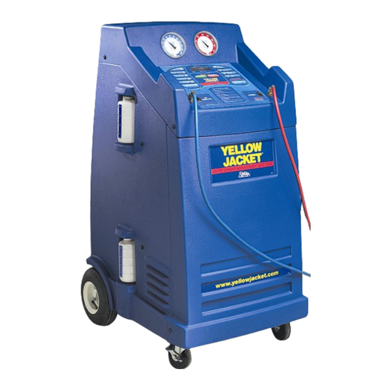
- Page 4 Component Location and Description 1. Touch Pad (Control Panel) Oil Inject Bottle 2. High Gauge 10. Tool Tray 3. Low Gauge 11. Main Power Switch 4. Auto High Side Hose (Red) 12. Oil Inject Switch 5. Auto Low Side Hose (Blue) 13.
- Page 5 Control Panel Features system. This mode is most often used prior to LCD Display opening an A/C system to atmosphere to replace The Liquid Crystal Display (LCD) display provides the a system component. unit operator with continual updates of the status of the Model 800.
-
Page 6: Mode 1: Recovery Only
To ensure quick, successful integration of the Model Step 2: FILL SOURCE TANK WITH REFRIGERANT 800 series into your shop, please follow these set-up (also see page 11) procedures before the first use of the unit. 1. Attach the tank refill adapter (Part No. 19153) to the R-134a virgin cylinder. -
Page 7: Mode 2: Vacuum
Mode 2– Vacuum The vacuum function of the 800 SERIES is designed to between Y and N. remove moisture from the automobile A/C system by pull- 9. The LCD should read “PUSH START.”... -
Page 8: Mode 3: Charge Only
8. Press START key to begin charging operations. NOTE: If desired, the gauges of the Model 800 The 800 Series will start the charge cycle. can now be used to aid investigation of an A/C system problem. Ensure the automobile A/C The LCD will display the charging process progress. -
Page 9: Mode 5: Oil Inject
Mode 4 – Full Cycle, cont. 7. Record the vacuum level shown on the low 13. Verify the message on the LCD reads “FULL pressure gauge and press START to begin the CYCLE COMPLETE.” vacuum hold time. The hold time will count down 14. -
Page 10: Purging Non-Condensable Gases
Mode 7– Refrigerant Management System, cont. The refrigerant management information is stored in Register 4: Refrigerant charged in last job. nine registers. To access the information, press Register 5: Run time of last job. Mode 7, REFRIGERANT MANAGEMENT SYSTEM. Register 6: Total amount of refrigerant recovered to Press INCREASE or DECREASE to cycle through the date. -
Page 11: Troubleshooting Information
4. Drain oil into the container. SET key will reset the reminder until the next sched- 5. Dispose of the oil properly. uled maintenance. 6. Refill the vacuum pump with YELLOW JACKET Check oil level when pump is running. (Quart Part no. Oil fill port... -
Page 12: Common Problems
Common Problems and Potential Solution Problem Possible Causes Possible Solutions • Service valves on hoses not properly installed • Check valve seals and threads and replace if needed. Model 800 cannot pull automobile A/C system on A/C system. • Replace valve seals and Schrader core depressor. into a vacuum •... -
Page 13: Lcd Error Messages
LCD Error Messages and Potential Solution Error Possible Causes Possible Solutions • • Hi Pressure Limit Service valves on hoses closed Open valves • • Schrader core on A/C system not depressing Replace Schrader core • • Tank Empty No refrigerant in storage tank Refill storage tank using Mode 6, Tank Refill •... -
Page 14: Repair Parts List
Warranty Information LIMITED WARRANTY ® Ritchie Engineering guarantees YELLOW JACKET products to be free of defective material and workmanship which would affect the life of the product under normal use for the purpose for which it was designed. This warranty does not cover items that have been altered, abused, misused, improperly maintained, or returned solely in need of field service maintenance.
Need help?
Do you have a question about the 800 Series and is the answer not in the manual?
Questions and answers