
Related Manuals for Hydronix Hydro-Probe SE

Summary of Contents for Hydronix Hydro-Probe SE
- Page 1 Hydro-Probe SE User Guide To re-order quote part number: HD0278 Revision: 2.1.0 Revision date: Jan 2020...
- Page 2 Neither the whole or any part of the information contained in nor the product described in this documentation may be adapted or reproduced in any material form except with the prior written approval of Hydronix Limited, hereinafter referred to as Hydronix.
- Page 3 +1 888 887 4822 (Toll Free) +1 231 439 5001 European Office Covers Central Europe, Russia and South Africa Tel: +49 2563 4858 Fax: +49 2563 5016 French Office Tel: +33 652 04 89 04 Hydro-Probe SE User Guide HD0278 Rev 2.1.0 3...
- Page 4 4 Hydro-Probe SE User Guide HD0278 Rev. 2.1.0...
- Page 5 Revision history Revision No Date Description of Change 2.0.0 July 2014 Major Product Update 2.1.0 Jan 2020 Address Change Hydro-Probe SE User Guide HD0278 Rev 2.1.0 5...
- Page 6 6 Hydro-Probe SE User Guide HD0278 Rev. 2.1.0...
-
Page 7: Table Of Contents
Appendix B Moisture Calibration Record Sheet..................55 Appendix C Brix Calibration Record Sheet ................... 57 Appendix D Document Cross Reference ....................59 Document Cross Reference ....................... 59 Hydro-Probe SE User Guide HD0278 Rev 2.1.0 7... - Page 8 8 Hydro-Probe SE User Guide HD0278 Rev. 2.1.0...
- Page 9 Figure 19: Relationship of moisture % to Unscaled values ..............30 Figure 20: Calibrations for 3 different materials (Left) and typical calibration data (Right) ....31 Figure 21: Calibration inside the Hydro-Probe SE ................33 Figure 22: Calibration inside the control system ................... 33 ...
-
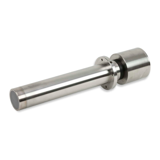
Page 10: Figure 1: The Hydro-Probe Se
USB Sensor Interface Module including cables and power supply EAK01 Ethernet Adapter Kit 3010 Mounting Boss 3020 Gasket (1 supplied with sensor) Hydro-Com configuration and diagnostics software is available for free download from www.hydronix.com 10 Hydro-Probe SE User Guide HD0278 Rev. 2.1.0... -
Page 11: Chapter 1 Introduction
Introduction 1 Introduction The Hydro-Probe SE is a digital microwave moisture / Brix sensor designed for use in higher temperature environments and pressurised vessels and to have a wear life of many years. The Hydro-Probe SE measures the material passing in front of the ceramic faceplate. Its on- board processing provides the options of both an analogue and a digital output which can be easily connected to any control system. -
Page 12: Sensor Connection And Configuration
Introduction 3 Sensor connection and configuration As with all Hydronix digital microwave sensors, the Hydro-Probe SE can be remotely configured using a digital serial connection and a PC running Hydro-Com diagnostics software. For communication with a PC, Hydronix supply RS232-485 converters, a USB Sensor Interface Module and an Ethernet Adapter Kit (see Chapter 3). -
Page 13: Chapter 2 Mechanical Installation
The optimum location for the sensor varies depending on the type of installation – a number of options are detailed on the following pages. Care should be taken to ensure that the Hydro-Probe SE has been correctly installed and in such a manner to ensure representative sampling of the material concerned. It is essential that the sensing part of the unit is fully inserted into the main flow of the material. -
Page 14: Figure 3: Mounting Boss
Chapter 2 Mechanical Installation Figure 3: Mounting Boss Mounting in a Vessel The Hydro-Probe SE can be installed in a vessel. Mounting Boss Pressure Vessel wall M6 Bolt Hydro-Probe SE Mounting Flange Pressure tight weld Gasket Figure 4: Mounting in a pressure vessel Material ... -
Page 15: Maintenance
Chapter 2 Mounting in a pipeline measurement chamber If the Hydro-Probe SE is to be installed in a measurement chamber in-line with a pipeline the chamber must remain completely full at all times to achieve reliable results. A bypass line should be installed to facilitate any maintenance of the sensor (Figure 6). - Page 16 Chapter 2 Mechanical Installation 16 Hydro-Probe SE User Guide HD0278 Rev. 2.1.0...
-
Page 17: Chapter 3 Electrical Installation And Communication
Chapter 3 Electrical installation and communication Hydronix supplies cable 0975 for use with the Hydro-Probe SE; this is available in different lengths. Any extension cable required should be connected to the Hydronix sensor cable using a suitable screened junction box. See Chapter 8 for details. -
Page 18: Figure 7: 0975 Sensor Cable Connections
Control Room Wiring Figure 7: 0975 Sensor cable connections Note: The cable screen is grounded at the sensor. It is important to ensure that the plant where the sensor is installed is properly grounded. 18 Hydro-Probe SE User Guide HD0278 Rev. 2.1.0... -
Page 19: Rs485 Multi-Drop Connection
Sensor cable Junction box Screen Do not connect screen at control cabinet. To PC or From plant other control sensors device Figure 8: RS485 multi-drop connections Figure 9: Multi-Drop RS485 wiring method Hydro-Probe SE User Guide HD0278 Rev 2.1.0 19... -
Page 20: Digital Input/Output Connections
Electrical installation and communication 4 Digital input/output connections The Hydro-Probe SE has two digital inputs, the second of which can also be used as an output for a known state. Full descriptions of how the digital inputs/outputs can be configured are... -
Page 21: Connecting To A Pc
16 sensors on a network. The converter has a terminal block for connecting the twisted pair RS485 A and B wires and can then be connected to a PC serial communication port. Figure 13: RS232/485 converter connections (0049A) Hydro-Probe SE User Guide HD0278 Rev 2.1.0 21... -
Page 22: Figure 14: Sim01 Usb-Rs485 Converter Connections
Figure 14: SIM01 USB-RS485 converter connections Ethernet Adapter Kit (Part no: EAK01) Manufactured by Hydronix, the Ethernet adapter is suitable for connecting up to 16 sensors to a standard Ethernet network. An optional Ethernet Power Adapter Kit (EPK01) is also available which eliminates the need for additional expensive cables to be run to a remote location which does not have local power. -
Page 23: Figure 16: Ethernet Power Adapter Kit Connections (Epk01)
Hydronix Part No: EPK01 Figure 16: Ethernet Power Adapter Kit connections (EPK01) Figure 17: Maximum number of sensor connections dependent upon ambient temperature NOTE: Operation above these limits may cause premature failure of the unit. Hydro-Probe SE User Guide HD0278 Rev 2.1.0 23... - Page 24 Chapter 3 Electrical installation and communication 24 Hydro-Probe SE User Guide HD0278 Rev. 2.1.0...
-
Page 25: Chapter 4 Configuration
Configuration 1 Configuring the Sensor The Hydro-Probe SE has a number of internal parameters which may be used to optimise the sensor for a given application. These settings are available to view and change using the Hydro- Com software. Information for all settings can be found in the Hydro-Com User Guide (HD0273). - Page 26 2.2.6 Material Temperature The Hydro-Probe SE has a temperature sensor attached to the metal of the sensing head. This can be used to output the current material temperature. The output value is set at 0°C equals 0mA (or 4mA dependent upon the output set-up) and 100°C equals 20 mA.
-
Page 27: Digital Inputs/Output Setup
An input is activated using 15 – 30V DC into the digital input connection. The sensor power supply may be used as an excitation supply for this, or alternatively an external source may be used as in Figure 10. Hydro-Probe SE User Guide HD0278 Rev 2.1.0 27... -
Page 28: Filtering
Moisture/Brix readings during this time should be excluded from the average value as they 28 Hydro-Probe SE User Guide HD0278 Rev. 2.1.0... -
Page 29: Alternative Measurement Modes
Low Limit. 5 Alternative Measurement Modes The Hydro-Probe SE has the option of selecting alternative measurement modes. The modes have been carefully designed to ensure that the sensor may be configured for maximum sensitivity across a wide variety of materials. -
Page 30: Figure 19: Relationship Of Moisture % To Unscaled Values
Data can easily be recorded using a PC and the Hydronix Hydro-Com software, these results may then be plotted in a spread sheet. When viewed in graph form it is often self-evident which mode gives the desired performance characteristics. -
Page 31: Chapter 5 Material Calibration
(0) value relates to the measurement in air and 100 relates to water. This is used to give a raw output value from a Hydronix sensor which ranges from 0 to 100 and is called the Unscaled value. -
Page 32: Storing Calibration Data
For further advice regarding specific applications please consult the Hydronix support team support@hydronix.com The Calibration Types The Hydro-Probe SE can be calibrated to a moisture percentage or a Brix Value. A material calibration for moisture is normally linear, and calibrating to this is described in Chapter 5 section 3. -
Page 33: Moisture (Linear) Calibration
No need to learn how to use additional software. If it is necessary to replace the sensor, a replacement Hydronix sensor can be connected and valid results obtained immediately without connecting the sensor to a PC to update the material calibration. -
Page 34: Figure 23: Calibration Line Example
Free moisture Total moisture The SSD Coefficient used in Hydronix procedures and equipment is a value that relates to the water absorption properties of the material, sometimes referred to as the Water Absorption Value (WAV). This value is determined by more complex means than oven drying and may usually be obtained from the material supplier. -
Page 35: Figure 24: Calibrations Using The Ssd Coefficient
Appendix B. The same principles apply with or without using Hydro- Com when calibrating. Sensor Settings Sensor settings are configured using Hydro-Com, available free from the Hydronix web site www.Hydronix.com. See the Hydro-Com user guide HD0273 for full instructions. - Page 36 Calculating the moisture content All calibrations in the user guide refer to the dry weight of the material. (Note that the moisture calculated here is based upon the dry weight.) 36 Hydro-Probe SE User Guide HD0278 Rev. 2.1.0...
-
Page 37: Figure 25: Example Of A Good Material Calibration
P oor M o isture C alibra tio n D ata Senso r U nscaled O utp ut Senso r U nscaled O utp ut Figure 26: Examples of poor material calibration points Hydro-Probe SE User Guide HD0278 Rev 2.1.0 37... -
Page 38: Brix Calibration
4 Brix Calibration The Hydro-Probe SE has the ability to derive the Brix content of a liquid from the Unscaled value. This is a measure of the amount of dissolved solids that are in a liquid and is mainly used in the food industry. -
Page 39: Figure 28: Unscaled And Brix Values Entered Into Hydro-Com
Three methods are given to ensure that the best possible fit may be achieved. The most commonly used is, ‘Use default starting point’. The other two methods may also be tried and the results viewed by eye (Figure 30). Hydro-Probe SE User Guide HD0278 Rev 2.1.0 39... -
Page 40: Figure 30: Hydro-Com Brix Calibration Best-Fit
When a calibration line has been calculated, it can be written to the sensor using the “Recalculate Seed Point/Update Sensor Calibration” button. Pressing this will display the following screen (Figure 31): Figure 31: Recalculate Seed point/Update sensor 40 Hydro-Probe SE User Guide HD0278 Rev. 2.1.0... -
Page 41: Figure 32: Example Of A Good Brix Calibration
If simply using the un-calibrated Filtered Unscaled output then the target point is set at the desired Unscaled value, this will be highly repeatable from batch to batch. Hydro-Probe SE User Guide HD0278 Rev 2.1.0 41... - Page 42 Write New Coefficients This button writes the, currently displayed, calibration to the sensor enabling the sensor to output a Brix value. For full details on the use of Hydro-Com see user guide HD0273. 42 Hydro-Probe SE User Guide HD0278 Rev. 2.1.0...
-
Page 43: Quadratic Calibration
Chapter 5 5 Quadratic calibration The Hydro-Probe SE is able to utilise a quadratic calibration function for use in the rare occasions where a material is non-linear. The equation used is show below: Moisture % = A x (Unscaled value)² + B (Unscaled value) + C – D... -
Page 44: Figure 35: Example Of A Good Quadratic Calibration
On the right hand graph the points are very close indicating a small spread in moisture % of the samples. This calibration requires additional calibration points to increase the spread and to improve the accuracy. Sensor Unscaled Figure 36: Examples of bad quadratic calibrations 44 Hydro-Probe SE User Guide HD0278 Rev. 2.1.0... -
Page 45: Chapter 6 Frequently Asked Questions
For granular or flowing materials check that the flow is consistent and that there is no build-up of material on the sensor. Hydro-Probe SE User Guide HD0278 Rev 2.1.0 45... - Page 46 Unscaled value drops to zero. The Calibrated output is only valid whilst the sensor is exposed to the material. What is the maximum length of cable I can use? See Chapter 8 Technical Specification. 46 Hydro-Probe SE User Guide HD0278 Rev. 2.1.0...
-
Page 47: Chapter 7 Sensor Diagnostics
Chapter 7 Sensor diagnostics The following tables list the most common faults found when using the sensor. If you are unable to diagnose the problem from this information, please contact Hydronix technical support. support@hydronix.com 1 Symptom: No output from sensor... -
Page 48: Symptom: Incorrect Analogue Output
Hydro- Com. Determine the Com Port number assigned to the actual port by looking at the PC device manager 48 Hydro-Probe SE User Guide HD0278 Rev. 2.1.0... -
Page 49: Symptom: Near Constant Material Reading
Sensor has shut down Disconnect power Normal operation is Check operating for 30 seconds and 70mA – 150 mA temperature is retry or measure within specified current drawn from range power supply Hydro-Probe SE User Guide HD0278 Rev 2.1.0 49... -
Page 50: Symptom: Inconsistent Or Erratic Readings That Do Not Track Material
Average/Hold input for the application behaviour OFF and changing with the input ON Inadequate ground Metalwork and Ground potential Ensure connections cable ground differences must be equipotential connections minimized bonding of metalwork 50 Hydro-Probe SE User Guide HD0278 Rev. 2.1.0... -
Page 51: Chapter 8 Technical Specification
0 – 60°C (32 - 140°F). The sensor will not work in frozen materials Operating Pressure The Hydro-Probe SE will operate from 1 bar Vacuum to 5 bar pressure. Power supply voltage 15 - 30 VDC. 1 A minimum required for start-up (normal operating power is 4W). -
Page 52: Connections
The sensor body is connected to the cable shield. Ensure equipotential bonding of all exposed metalwork (see Chapter 3). In areas of high lightning risk, correct and adequate protection should be used. Contact Hydronix support for recommended lightning protection. Emissions EEC Declaration of Conformity Electromagnetic Compatibility Directive 2004/108/EC 52 Hydro-Probe SE User Guide HD0278 Rev. -
Page 53: Appendix A Default Parameters
Unscaled 2 Type As above Mode V Smoothing time 1.0, 2.5, 5.0, 7.5, 10 1 sec Slew rate + Light Light Medium Heavy Unused Slew rate - Light Light Medium Heavy Unused Hydro-Probe SE User Guide HD0278 Rev 2.1.0 53... - Page 54 Input Use 1 Unused Moisture/Temp Average/hold Moisture/temp Input/output Use 2 Unused Unused Moisture temp Bin empty Data invalid Probe OK Temperature compensation Electronics temp. coeff. Factory set Resonator temp. coeff. Factory set 54 Hydro-Probe SE User Guide HD0278 Rev. 2.1.0...
-
Page 55: Appendix B Moisture Calibration Record Sheet
Data may be used to recalibrate the sensor if there are consistent errors in moisture (>0.5%) between the current moisture output from the sensor and the lab moisture. Material Location Sensor S/N Readings from sensor Lab. Sensor/Lab moisture moisture difference Operator name Date Time Unscaled Moisture Hydro-Probe SE User Guide HD0278 Rev 2.1.0 55... - Page 56 Appendix B Moisture Calibration Record Sheet 56 Hydro-Probe SE User Guide HD0278 Rev. 2.1.0...
-
Page 57: Appendix C Brix Calibration Record Sheet
Data may be used to recalibrate the sensor if there are consistent errors in Brix between the current moisture output from the sensor and the lab Brix. Material Location Sensor S/N Readings from sensor Lab. Sensor/Lab Brix Brix Operator name Date Time Unscaled Moisture difference Hydro-Probe SE User Guide HD0278 Rev 2.1.0 57... - Page 58 Appendix C Brix Calibration Record Sheet 58 Hydro-Probe SE User Guide HD0278 Rev. 2.1.0...
-
Page 59: Appendix D Document Cross Reference
Document Number Title HD0273 Hydro-Com User Guide HD0303 USB Sensor Interface Module User Guide HD0333 Ethernet Adapter User Guide EN0058 HPSE Default Values Hydro-Probe SE User Guide HD0278 Rev 2.1.0 59... - Page 60 Appendix D Document Cross Reference 60 Hydro-Probe SE User Guide HD0278 Rev. 2.1.0...
- Page 61 Ethernet Adapter ........22 Sensor Cable ..........18 RS232/485 ..........21 Suitable Applications........11 USB Sensor Interface Module ....22 Wear life ............11 Default parameters ........53 Digital Inputs/Output Average/Hold ..........27 Hydro-Probe SE User Guide HD0278 Rev 2.1.0 61...
Need help?
Do you have a question about the Hydro-Probe SE and is the answer not in the manual?
Questions and answers