Table of Contents
Advertisement
Quick Links
Advertisement
Table of Contents

Related Manuals for Alphi CPCI-AD32

Summary of Contents for Alphi CPCI-AD32
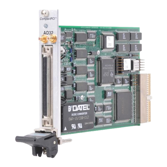
- Page 1 CPCI-AD32 Intelligent DSP Based 32 Channel Analog Input Card for 3U CompactPCI CompactPCI™ systems REFERENCE MANUAL 751-10-000-4000 Version 1.0 September 1998 ALPHI TECHNOLOGY CORPORATION 6202 S. Maple Avenue #120 Tempe, AZ 85283 USA Tel: (602) 838-2428 Fax: (602) 838-4477...
- Page 2 ALPHI TECHNOLOGY reserves the right to make any changes, without notice, to this or any of ALPHI TECHNOLOGY’ s products to improve reliability, performance, function or design.
-
Page 3: Table Of Contents
5.5 RESERVED (P4, P5) _____________________________________________________ 14 5.6 32 BIT CPCI BUS (J1) ____________________________________________________ 14 STANDALONE OPERATION ___________________________________________14 6.1 CPCI RESET ___________________________________________________________ 14 6.2 CPCI BUS CLOCK _______________________________________________________ 14 ALPHI TECHNOLOGY CORP. Page iii REV 1.0 751-10-000-4000 Part Number : Copyright ALPHI Technology Corporation, 1998... -
Page 4: General Description
The CPCI-AD32 is an intelligent DSP based 32 channel analog input card in a 3U CPCI form factor. The CPCI-AD32 provides up to 32 single ended or 16 differential inputs to a 16 bit converter. The DSP allows for the offloading from the HOST CPU any necessary I/O processing to monitor and service these channels. - Page 5 8 Differential 10 uS Input Multiplexer A/D Conv 8 bit and Conditioning Digital Port Figure 1.1: Block Diagram Figure 1.2: Jumper and Connector Locations ALPHI TECHNOLOGY CORP. Page 2 REV 1.0 751-10-000-4000 Part Number : Copyright ALPHI Technology Corporation, 1998...
-
Page 6: Reference Materials List
WindowsNT and Windows95 Programming Tools: BlueWater Systems 144 Railroad Ave. Suite #217 Edmonds, WA 98020 Tel: (206) 771-3610 Fax: (206) 771-2742 E-Mail: info@bluewatersystems.com Web: http://www.bluewatersystems.com ALPHI TECHNOLOGY CORP. Page 3 REV 1.0 751-10-000-4000 Part Number : Copyright ALPHI Technology Corporation, 1998... -
Page 7: Host (Cpci) Side
NOTE: The AMCC has been programmed to request memory above 1 Mbytes. 2.3 CPCI OPERATION REGISTERS The host processor communicates with the CPCI-AD32 card via the AMCC pass-through interface. After the base address register has been programmed by the CPCI configurator, incoming CPCI I/O or Memory cycles are used to access the registers of the AMCC chip. -
Page 8: C31 Side
For more information about these registers refer to the AMCC PCI controller manual. C31 SIDE 3.1 INTERNAL ORGANIZATION The CPCI-AD32 card is divided into different sections. Each section and its relationship to other sections will be discussed. The CPCI-AD32 sections are: • CPCI interface •... - Page 9 HOST and DSP of that half of the CPCI-AD32 module. Interrupts can be enabled based on a specific mailbox event. There are 4 incoming mailboxes and 4 outgoing mailboxes. Each mailbox is 32 bits wide.
-
Page 10: Dsp Memory And Register Map Summary
Writes to STROBE will trigger conversion. TCLK0 from DSP will trigger conversion. EXTRIG will trigger conversion. Both TCLK0 and EXTRIG will trigger conversion. Table 3.4: Signal routing to STRB_OUT ALPHI TECHNOLOGY CORP. Page 7 REV 1.0 751-10-000-4000 Part Number : Copyright ALPHI Technology Corporation, 1998... - Page 11 When this bit is cleared to a 0, the output jacks and the signals fed back to the A/D converters for calibration are grounded. When this bit is set to a 1, the DAC outputs function normally. ALPHI TECHNOLOGY CORP. Page 8 REV 1.0 751-10-000-4000 Part Number : Copyright ALPHI Technology Corporation, 1998...
- Page 12 BIT 05 BIT 04 BIT 03 BIT 02 BIT 01 BIT 00 CAL1 DIFF2 G2_01 G2_00 CAL0 DIFF1 G1_01 G1_00 CAL1, CAL0 Calibration source ALPHI TECHNOLOGY CORP. Page 9 REV 1.0 751-10-000-4000 Part Number : Copyright ALPHI Technology Corporation, 1998...
- Page 13 Gain Selection Input gains are selected on a per channel basis according to the following table. Gx_01 Gx_00 Gain Selected Table 3.X: Gain Selection ALPHI TECHNOLOGY CORP. Page 10 REV 1.0 751-10-000-4000 Part Number : Copyright ALPHI Technology Corporation, 1998...
-
Page 14: Reset Signals
CPCI-AD32 REFERENCE MANUAL 3.4 RESET SIGNALS The CPCI-AD32 can be reset from two different sources: • At power on or when the PCI RESET is asserted, the watchdog timer will hold the C31 RESET line low for 200 mS. • The AMCC has a bit called SYSRST which the HOST can toggle to reset the DSP and internal logic. -
Page 15: Connections
A 80 pin subminiature D shelled connector is used to route all the analog and digital signals off the card. ALPHI Technology can supply transition modules and cable assemblies to meet any special requirements. Contact the factory for additional information. - Page 16 AD SAMPLE CLK IN D_GND D_GND PA_07 PB_07 PA_06 PB_06 PA_05 PB_05 PA_04 PB_04 PA_03 PB_03 PA_02 PB_02 PA_01 PB_01 PA_00 PB_00 Table 5.2: External I/O Connector ALPHI TECHNOLOGY CORP. Page 13 REV 1.0 751-10-000-4000 Part Number : Copyright ALPHI Technology Corporation, 1998...
-
Page 17: Dac Outputs (P1, P2)
This is accomplished by inserting a jumper in location W9 for stand alone operation. In a hosted environment, it must be removed. ALPHI TECHNOLOGY CORP. Page 14 REV 1.0 751-10-000-4000 Part Number : Copyright ALPHI Technology Corporation, 1998...
Need help?
Do you have a question about the CPCI-AD32 and is the answer not in the manual?
Questions and answers