Table of Contents
Advertisement
Advertisement
Table of Contents

Related Manuals for ASROCK Velocita Z490 PG


Summary of Contents for ASROCK Velocita Z490 PG
- Page 2 (including damages for loss of profits, loss of business, loss of data, interruption of business and the like), even if ASRock has been advised of the possibility of such damages arising from any defect or error in the documentation or product.
- Page 3 You are also entitled to have the goods repaired or replaced if the goods fail to be of acceptable quality and the failure does not amount to a major failure. If you require assistance please call ASRock Tel : +886-2-28965588 ext.123 (Standard International call charges apply) The terms HDMI®...
-
Page 4: Table Of Contents
Contents Chapter 1 Introduction Package Contents Specifications Motherboard Layout I/O Panel Chapter 2 Installation Installing the CPU Installing the CPU Fan and Heatsink Installing Memory Modules (DIMM) Expansion Slots (PCI Express Slots) MOS Heatsink Height Jumpers Setup Onboard Headers and Connectors Smart Switches Dr. - Page 5 Chapter 3 Software and Utilities Operation Installing Drivers ASRock Motherboard Utility (Phantom Gaming Tuning) 3.2.1 Installing ASRock Motherboard Utility (Phantom Gaming Tuning) 3.2.2 Using ASRock Motherboard Utility (Phantom Gaming Tuning) ASRock Live Update & APP Shop 3.3.1 UI Overview 3.3.2 Apps 3.3.3...
- Page 6 4.6.3 Storage Configuration 4.6.4 Intel(R) Thunderbolt 4.6.5 Super IO Configuration 4.6.6 ACPI Configuration 4.6.7 USB Configuration 4.6.8 Trusted Computing Tools Hardware Health Event Monitoring Screen Security Screen 4.10 Boot Screen 4.11 Exit Screen...
-
Page 7: Chapter 1 Introduction
If you require technical support related to this mother- board, please visit our website for specific information about the model you are using. You may find the latest VGA cards and CPU support list on ASRock’s website as well. ASRock website http://www.asrock.com. -
Page 8: Specifications
• 4 x DDR4 DIMM Slots • Supports DDR4 4666+(OC)*/4600/4500/4400/4333/4266 (OC)/4133(OC)/4000(OC)/3866(OC)/3800(OC)/3733(OC)/ 3600(OC)/3200(OC)/2933/2800/2666/2400/2133 non-ECC, un-buffered memory * Please refer to Memory Support List on ASRock's website for more information. (http://www.asrock.com/) * Core (i9/i7) support DDR4 up to 2933; Core (i5/i3), Pentium® and Celeron® support DDR4 up to 2666. - Page 9 Z490 PG Velocita • 15μ Gold Contact in VGA PCIe Slot (PCIE1) Graphics • Intel® UHD Graphics Built-in Visuals and the VGA outputs can be supported only with processors which are GPU integrated. • Hardware Accelerated Codecs: AVC/H.264, HEVC/H.265 8bit, HEVC/H.265 10bit, VP8, VP9 8bit, VP9 10bit, MPEG 2, MJPEG, VC-1 * VP9 10bit and VC-1 are for decode only.
- Page 10 • Gold Audio Jacks • 15μ Gold Audio Connector • Nahimic Audio 1 x 2.5 Gigabit LAN 10/100/1000/2500 Mb/s (Dragon RTL8125BG) • Supports Phantom Gaming LAN Software - Smart Auto Adjust Bandwidth Control - Visual User Friendly UI - Visual Network Usage Statistics - Optimized Default Setting for Game, Browser, and Streaming Modes - User Customized Priority Control...
- Page 11 M.2 PCI Express module up to Gen3 x4 (32 Gb/s)** ** Supports Intel® Optane Technology ** Supports NVMe SSD as boot disks ** Supports ASRock U.2 Kit Connector • 1 x SPI TPM Header • 1 x Power LED and Speaker Header • 2 x RGB LED Headers...
- Page 12 Connector) • 1 x Front Panel Audio Connector (15μ Gold Audio Connector) • 1 x Thunderbolt AIC Connector (5-pin) (Supports ASRock Thunderbolt 3 AIC R2.0 Card only) • 2 x USB 2.0 Headers (Support 4 USB 2.0 ports) (Intel® Z490) (Supports ESD Protection) • 2 x USB 3.2 Gen1 Headers (Support 4 USB 3.2 Gen1 ports)
- Page 13 • ErP/EuP ready (ErP/EuP ready power supply is required) * For detailed product information, please visit our website: http://www.asrock.com Please realize that there is a certain risk involved with overclocking, including adjusting the setting in the BIOS, applying Untied Overclocking Technology, or using third-party overclocking tools.
-
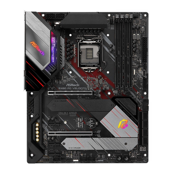
Page 14: Motherboard Layout
1.3 Motherboard Layout ADDR_LED2 CPU_FAN2/WP_3A ATX12V1 ATX12V2 CPU_FAN1 USB 3.2 Gen1 Top: 2.5GLAN T: USB3 (Realtek B: USB4 RTL8125AG) USB 3.2 Gen2 Top: T: USB31_TA_1 RJ-45 B: USB31_TC_1 (I219V) CHA_FAN5/WP RGB_LED2 CHA_FAN1/WP Z490 PG Velocita P C I E1 CT24 CT23 CT13 CT14... - Page 15 Z490 PG Velocita No. Description 8 pin 12V Power Connector (ATX12V1) 8 pin 12V Power Connector (ATX12V2) CPU Fan Connector (CPU_FAN1) 2 x 288-pin DDR4 DIMM Slots (DDR4_A1, DDR4_B1) 2 x 288-pin DDR4 DIMM Slots (DDR4_A2, DDR4_B2) CPU/Water Pump Fan Connector (CPU_FAN2/WP_3A) Addressable LED Header (ADDR_LED2) ATX Power Connector (ATXPWR1) Chassis/Water Pump Fan Connector (CHA_FAN5/WP)
-
Page 16: I/O Panel
1.4 I/O Panel No. Description No. Description PS/2 Mouse/Keyboard Port Optical SPDIF Out Port 2.5G LAN RJ-45 Port Antenna Ports (Dragon RTL8125BG)* USB 3.2 Gen2 Type-A Port (USB31_TA_1) LAN RJ-45 Port (Intel® I219V)** USB 3.2 Gen2 Type-C Port (USB31_TC_1) Central / Bass (Orange) USB 3.2 Gen1 Ports (USB3_34)**** Rear Speaker (Black) USB 3.2 Gen1 Ports (USB3_12) - Page 17 Z490 PG Velocita * There are two LEDs on each LAN port. Please refer to the table below for the LAN port LED indications. ACT/LINK LED SPEED LED LAN Port Activity / Link LED Speed LED Status Description Status Description No Link 10Mbps connection 100Mbps/1Gbps...
-
Page 18: Chapter 2 Installation
Chapter 2 Installation This is an ATX form factor motherboard. Before you install the motherboard, study the configuration of your chassis to ensure that the motherboard fits into it. Pre-installation Precautions Take note of the following precautions before you install motherboard components or change any motherboard settings. -
Page 19: Installing The Cpu
Z490 PG Velocita 2.1 Installing the CPU 1. Before you insert the 1200-Pin CPU into the socket, please check if the PnP cap is on the socket, if the CPU surface is unclean, or if there are any bent pins in the socket. Do not force to insert the CPU into the socket if above situation is found. - Page 21 Z490 PG Velocita Please save and replace the cover if the processor is removed. The cover must be placed if you wish to return the motherboard for after service.
-
Page 22: Installing The Cpu Fan And Heatsink
2.2 Installing the CPU Fan and Heatsink... -
Page 23: Installing Memory Modules (Dimm)
Z490 PG Velocita 2.3 Installing Memory Modules (DIMM) This motherboard provides four 288-pin DDR4 (Double Data Rate 4) DIMM slots, and supports Dual Channel Memory Technology. 1. For dual channel configuration, you always need to install identical (the same brand, speed, size and chip-type) DDR4 DIMM pairs. -
Page 25: Expansion Slots (Pci Express Slots)
Z490 PG Velocita 2.4 Expansion Slots (PCI Express Slots) There are 5 PCI Express slots on the motherboard. Before installing an expansion card, please make sure that the power supply is switched off or the power cord is unplugged. Please read the documentation of the expansion card and make necessary hardware settings for the card before you start the installation. -
Page 26: Mos Heatsink Height
2.5 MOS Heatsink Height MOS-N Heatsink Height 40.5 mm... -
Page 27: Jumpers Setup
Z490 PG Velocita 2.6 Jumpers Setup The illustration shows how jumpers are setup. When the jumper cap is placed on the pins, the jumper is “Short”. If no jumper cap is placed on the pins, the jumper is “Open”. Clear CMOS Jumper Short: Clear CMOS (CLRMOS1) Open: Default... -
Page 28: Onboard Headers And Connectors
2.7 Onboard Headers and Connectors Onboard headers and connectors are NOT jumpers. Do NOT place jumper caps over these headers and connectors. Placing jumper caps over the headers and connectors will cause permanent damage to the motherboard. System Panel Header Connect the power PLED+ PLED-... - Page 29 Z490 PG Velocita Power LED and Speaker Please connect the SPEAKER DUMMY Header chassis power LED and DUMMY (7-pin SPK_PLED1) the chassis speaker to this (see p.8, No. 18) header. PLED+ PLED+ PLED- Serial ATA3 Connectors These eight SATA3 (SATA3_0_1: connectors support SATA see p.8, No.
- Page 30 USB 3.2 Gen1 Headers There are two headers on (19-pin USB3_5_6) this motherboard. Each Dummy IntA_PA_D+ (see p.8, No. 13) IntA_PB_D+ IntA_PA_D- USB 3.2 Gen1 header can IntA_PB_D- support two ports. IntA_PA_SSTX+ IntA_PB_SSTX+ IntA_PA_SSTX- IntA_PB_SSTX- IntA_PA_SSRX+ IntA_PB_SSRX+ IntA_PA_SSRX- IntA_PB_SSRX- Vbus Vbus (19-pin USB3_7_8) Vbus...
- Page 31 Z490 PG Velocita High Definition Audio supports Jack Sensing, but the panel wire on the chassis must sup- port HDA to function correctly. Please follow the instructions in our manual and chassis manual to install your system. Chassis/Water Pump Fan This motherboard Connectors provides five 4-Pin water...
- Page 32 ATX Power Connector This motherboard pro- (24-pin ATXPWR1) vides a 24-pin ATX power (see p.8, No. 8) connector. To use a 20-pin ATX power supply, please plug it along Pin 1 and Pin ATX 12V Power This motherboard Connectors provides two 8-pin ATX (8-pin ATX12V1) 12V power connectors.
- Page 33 Z490 PG Velocita RGB LED Headers These two RGB headers are used (4-pin RGB_LED1) to connect RGB LED extension (see p.8, No. 27) 12V G R cable which allows users to choose from various LED lighting effects. (4-pin RGB_LED2) Caution: Never install the RGB LED cable in the wrong orienta- (see p.8, No.
-
Page 34: Smart Switches
2.8 Smart Switches The motherboard has two smart switches: Power Button and Reset Button, allowing users to quickly turn on/off the system or reset the system. Power Button Power Button allows users (PWRBTN1) to quickly turn on/off the (see p.8, No. 21) system. -
Page 35: Dr. Debug
Z490 PG Velocita 2.9 Dr. Debug Dr. Debug is used to provide code information, which makes troubleshooting even easier. Please see the diagrams below for reading the Dr. Debug codes. Code Description 0x10 PEI_CORE_STARTED 0x11 PEI_CAR_CPU_INIT 0x15 PEI_CAR_NB_INIT 0x19 PEI_CAR_SB_INIT 0x31 PEI_MEMORY_INSTALLED 0x32... - Page 36 0x63 DXE_CPU_INIT 0x68 DXE_NB_HB_INIT 0x69 DXE_NB_INIT 0x6A DXE_NB_SMM_INIT 0x70 DXE_SB_INIT 0x71 DXE_SB_SMM_INIT 0x72 DXE_SB_DEVICES_INIT 0x78 DXE_ACPI_INIT 0x79 DXE_CSM_INIT 0x90 DXE_BDS_STARTED 0x91 DXE_BDS_CONNECT_DRIVERS 0x92 DXE_PCI_BUS_BEGIN 0x93 DXE_PCI_BUS_HPC_INIT 0x94 DXE_PCI_BUS_ENUM 0x95 DXE_PCI_BUS_REQUEST_RESOURCES 0x96 DXE_PCI_BUS_ASSIGN_RESOURCES 0x97 DXE_CON_OUT_CONNECT 0x98 DXE_CON_IN_CONNECT...
- Page 37 Z490 PG Velocita 0x99 DXE_SIO_INIT 0x9A DXE_USB_BEGIN 0x9B DXE_USB_RESET 0x9C DXE_USB_DETECT 0x9D DXE_USB_ENABLE 0xA0 DXE_IDE_BEGIN 0xA1 DXE_IDE_RESET 0xA2 DXE_IDE_DETECT 0xA3 DXE_IDE_ENABLE 0xA4 DXE_SCSI_BEGIN 0xA5 DXE_SCSI_RESET 0xA6 DXE_SCSI_DETECT 0xA7 DXE_SCSI_ENABLE 0xA8 DXE_SETUP_VERIFYING_PASSWORD 0xA9 DXE_SETUP_START 0xAB DXE_SETUP_INPUT_WAIT 0xAD DXE_READY_TO_BOOT 0xAE DXE_LEGACY_BOOT...
- Page 38 0xAF DXE_EXIT_BOOT_SERVICES 0xB0 RT_SET_VIRTUAL_ADDRESS_MAP_BEGIN 0xB1 RT_SET_VIRTUAL_ADDRESS_MAP_END 0xB2 DXE_LEGACY_OPROM_INIT 0xB3 DXE_RESET_SYSTEM 0xB4 DXE_USB_HOTPLUG 0xB5 DXE_PCI_BUS_HOTPLUG 0xB6 DXE_NVRAM_CLEANUP 0xB7 DXE_CONFIGURATION_RESET 0xF0 PEI_RECOVERY_AUTO 0xF1 PEI_RECOVERY_USER 0xF2 PEI_RECOVERY_STARTED 0xF3 PEI_RECOVERY_CAPSULE_FOUND 0xF4 PEI_RECOVERY_CAPSULE_LOADED 0xE0 PEI_S3_STARTED 0xE1 PEI_S3_BOOT_SCRIPT 0xE2 PEI_S3_VIDEO_REPOST...
- Page 39 Z490 PG Velocita 0xE3 PEI_S3_OS_WAKE 0x50 PEI_MEMORY_INVALID_TYPE 0x53 PEI_MEMORY_NOT_DETECTED 0x55 PEI_MEMORY_NOT_INSTALLED 0x57 PEI_CPU_MISMATCH 0x58 PEI_CPU_SELF_TEST_FAILED 0x59 PEI_CPU_NO_MICROCODE 0x5A PEI_CPU_ERROR 0x5B PEI_RESET_NOT_AVAILABLE 0xD0 DXE_CPU_ERROR 0xD1 DXE_NB_ERROR 0xD2 DXE_SB_ERROR 0xD3 DXE_ARCH_PROTOCOL_NOT_AVAILABLE 0xD4 DXE_PCI_BUS_OUT_OF_RESOURCES 0xD5 DXE_LEGACY_OPROM_NO_SPACE 0xD6 DXE_NO_CON_OUT 0xD7 DXE_NO_CON_IN...
- Page 40 0xD8 DXE_INVALID_PASSWORD 0xD9 DXE_BOOT_OPTION_LOAD_ERROR 0xDA DXE_BOOT_OPTION_FAILED 0xDB DXE_FLASH_UPDATE_FAILED 0xDC DXE_RESET_NOT_AVAILABLE 0xE8 PEI_MEMORY_S3_RESUME_FAILED 0xE9 PEI_S3_RESUME_PPI_NOT_FOUND 0xEA PEI_S3_BOOT_SCRIPT_ERROR 0xEB PEI_S3_OS_WAKE_ERROR...
-
Page 41: Tm Tm
Z490 PG Velocita 2.10 CrossFireX and Quad CrossFireX Operation Guide This motherboard supports CrossFireX and Quad CrossFireX that allows you to install up to two identical PCI Express x16 graphics cards. 1. You should only use identical CrossFireX -ready graphics cards that are AMD certified. 2. - Page 42 Step 3 Connect a VGA cable or a DVI cable to the monitor connector or the DVI connec- tor of the graphics card that is inserted to PCIE1 slot.
-
Page 43: Driver Installation And Setup
Z490 PG Velocita 2.10.2 Driver Installation and Setup Step 1 Power on your computer and boot into OS. Step 2 Remove the AMD drivers if you have any VGA drivers installed in your system. The Catalyst Uninstaller is an optional download. We recommend using this utility to un- install any previously installed Catalyst drivers prior to installation. -
Page 44: Wifi/Bt Module And Intel® Cnvi (Integrated Wifi/Bt)
2.11 M.2 WiFi/BT Module and Intel® CNVi (Integrated WiFi/BT) Installation Guide (M2_WIFI) The M.2, also known as the Next Generation Form Factor (NGFF), is a small size and versatile card edge connector that aims to replace mPCIe and mSATA. The M.2 Socket (Key E) supports type 2230 WiFi/BT module and Intel®... - Page 45 Z490 PG Velocita Step 3 Gently insert the WiFi/BT module or Intel® CNVi (Integrated WiFi/ BT) into the M.2 slot. Please be aware that the module only fits in one orientation. Step 4 Tighten the screw with a screwdriver to secure the module into place. Please do not overtighten the screw as this might damage the module.
- Page 46 2.12 M.2_SSD (NGFF) Module Installation Guide (M2_2) The M.2, also known as the Next Generation Form Factor (NGFF), is a small size and versatile card edge connector that aims to replace mPCIe and mSATA. The Ultra M.2 Socket (M2_2) supports 2260/2280 M.2 SATA3 6.0 Gb/s module and M.2 PCI Express module up to Gen3 x4 (32 Gb/s).
- Page 47 Z490 PG Velocita Step 3 Before installing a M.2 (NGFF) SSD module, please loosen the screws to remove the M.2 heatsink. *Please remove the protective films on the bottom side of the M.2 heatsink before you install a M.2 SSD module. Step 4 Prepare the M.2 standoff that comes with the package.
- Page 48 M.2_SSD (NGFF) Module Support List (M2_2) Vendor Interface ADATA SATA3 AXNS381E-128GM-B ADATA SATA3 AXNS381E-256GM-B ADATA SATA3 ASU800NS38-256GT-C ADATA SATA3 ASU800NS38-512GT-C ADATA PCIe3 x4 ASX7000NP-128GT-C ADATA PCIe3 x4 ASX8000NP-256GM-C ADATA PCIe3 x4 ASX7000NP-256GT-C ADATA PCIe3 x4 ASX8000NP-512GM-C ADATA PCIe3 x4 ASX7000NP-512GT-C Apacer PCIe3 x4 AP240GZ280...
- Page 49 SATA3 VLM100-120G-2280B-RD V-Color SATA3 VLM100-240G-2280RGB V-Color SATA3 VSM100-240G-2280 V-Color SATA3 VLM100-240G-2280B-RD SATA3 WDS100T1B0B-00AS40 SATA3 WDS240G1G0B-00RC30 PCIe3 x4 WDS256G1X0C-00ENX0 (NVME) PCIe3 x4 WDS512G1X0C-00ENX0 (NVME) For the latest updates of M.2_SSD (NFGG) module support list, please visit our website for details: http://www.asrock.com...
-
Page 50: M.2_Ssd (Ngff) Module Installation Guide (M2_3)
2.13 M.2_SSD (NGFF) Module Installation Guide (M2_3) The M.2, also known as the Next Generation Form Factor (NGFF), is a small size and versatile card edge connector that aims to replace mPCIe and mSATA. The Ultra M.2 Socket (M2_3) supports type 2230/2242/2260/2280/22110 M.2 SATA3 6.0 Gb/s module and M.2 PCI Express module up to Gen3 x4 (32 Gb/s). - Page 51 Z490 PG Velocita Step 3 Before installing a M.2 (NGFF) SSD module, please loosen the screws to remove the M.2 heatsink. *Please remove the protective films on the bottom side of the M.2 heatsink before you install a M.2 SSD module. Step 4 Prepare the M.2 standoff that comes with the package.
- Page 52 M.2_SSD (NGFF) Module Support List Vendor Interface ADATA SATA3 AXNS330E-32GM-B ADATA SATA3 AXNS381E-128GM-B ADATA SATA3 AXNS381E-256GM-B ADATA SATA3 ASU800NS38-256GT-C ADATA SATA3 ASU800NS38-512GT-C ADATA PCIe3 x4 ASX7000NP-128GT-C ADATA PCIe3 x4 ASX8000NP-256GM-C ADATA PCIe3 x4 ASX7000NP-256GT-C ADATA PCIe3 x4 ASX8000NP-512GM-C ADATA PCIe3 x4 ASX7000NP-512GT-C Apacer PCIe3 x4...
- Page 53 SATA3 VLM100-120G-2280B-RD V-Color SATA3 VLM100-240G-2280RGB V-Color SATA3 VSM100-240G-2280 V-Color SATA3 VLM100-240G-2280B-RD SATA3 WDS100T1B0B-00AS40 SATA3 WDS240G1G0B-00RC30 PCIe3 x4 WDS256G1X0C-00ENX0 (NVME) PCIe3 x4 WDS512G1X0C-00ENX0 (NVME) For the latest updates of M.2_SSD (NFGG) module support list, please visit our website for details: http://www.asrock.com...
-
Page 54: Chapter 3 Software And Utilities Operation
Chapter 3 Software and Utilities Operation 3.1 Installing Drivers The Support CD that comes with the motherboard contains necessary drivers and useful utilities that enhance the motherboard’s features. Running The Support CD To begin using the support CD, insert the CD into your CD-ROM drive. The CD automatically displays the Main Menu if “AUTORUN”... -
Page 55: Asrock Motherboard Utility (Phantom Gaming Tuning)
Gaming Tuning) ASRock Motherboard Utility (Phantom Gaming Tuning) can be downloaded from ASRock Live Update & APP Shop. After the installation, you will find the icon “AS- Rock Motherboard Utility (Phantom Gaming Tuning)“ on your desktop. Double- click the “ASRock Motherboard Utility (Phantom Gaming Tuning)“... - Page 56 OC Tweaker Configurations for overclocking the system. System Info View information about the system. *The System Browser tab may not appear for certain models.
- Page 57 Settings Configure ASRock ASRock Motherboard Utility (Phantom Gaming Tuning). Click to select "Auto run at Windows Startup" if you want ASRock Motherboard Utility (Phantom Gaming Tuning) to be launched when you start up the Windows operating system.
-
Page 58: Asrock Live Update & App Shop
Double-click on your desktop to access ASRock Live Update & APP Shop utility. *You need to be connected to the Internet to download apps from the ASRock Live Update & APP Shop. 3.3.1 UI Overview Category Panel Hot News... -
Page 59: Apps
Z490 PG Velocita 3.3.2 Apps When the "Apps" tab is selected, you will see all the available apps on screen for you to download. Installing an App Step 1 Find the app you want to install. The most recommended app appears on the left side of the screen. The other various apps are shown on the right. - Page 60 Step 3 If you want to install the app, click on the red icon to start downloading. Step 4 When installation completes, you can find the green "Installed" icon appears on the upper right corner. To uninstall it, simply click on the trash can icon *The trash icon may not appear for certain apps.
- Page 61 Z490 PG Velocita Upgrading an App You can only upgrade the apps you have already installed. When there is an available new version for your app, you will find the mark of "New Version" appears below the installed app icon. Step 1 Click on the app icon to see more details.
-
Page 62: Bios & Drivers
3.3.3 BIOS & Drivers Installing BIOS or Drivers When the "BIOS & Drivers" tab is selected, you will see a list of recommended or critical updates for the BIOS or drivers. Please update them all soon. Step 1 Please check the item information before update. Click on to see more details. -
Page 63: Setting
Z490 PG Velocita 3.3.4 Setting In the "Setting" page, you can change the language, select the server location, and determine if you want to automatically run the ASRock Live Update & APP Shop on Windows startup. -
Page 64: Nahimic Audio
3.4 Nahimic Audio Nahimic audio software provides an incredible high definition sound technology which boosts the audio and voice performance of your system. Nahimic Audio interface is composed of four tabs : Audio, Microphone, Sound Tracker and Settings. There are four functions in Nahimic audio : Function Description From this tab, you can mute the current audio device, choose... -
Page 65: Asrock Polychrome Sync
Z490 PG Velocita 3.5 ASRock Polychrome SYNC ASRock Polychrome SYNC is a lighting control utility specifically designed for unique indi- viduals with sophisticated tastes to build their own stylish colorful lighting system. Simply by connecting the LED strip, you can customize various lighting schemes and patterns, including Static, Breathing, Strobe, Cycling, Music, Wave and more. - Page 66 Connecting the Addressable RGB LED Strip Connect your Addressable RGB LED strips to the Addressable LED Headers (ADDR_LED1, ADDR_LED2) on the motherboard. ADDR_LED2 DO_ADDR VOUT Z490 PG Velocita LA N ADDR_LED1 DO_ADDR VOUT 1. Never install the RGB LED cable in the wrong orientation; otherwise, the cable may be damaged.
- Page 67 ASRock Polychrome SYNC Utility Now you can adjust the RGB LED color through the ASRock Polychrome SYNC Utility. Download this utility from the ASRock Live Update & APP Shop and start coloring your PC style your way! Drag the tab to customize your preference.
-
Page 68: Chapter 4 Uefi Setup Utility
Chapter 4 UEFI SETUP UTILITY 4.1 Introduction This section explains how to use the UEFI SETUP UTILITY to configure your system. You may run the UEFI SETUP UTILITY by pressing <F2> or <Del> right after you power on the computer, otherwise, the Power-On-Self-Test (POST) will continue with its test routines. -
Page 69: Ez Mode
Z490 PG Velocita 4.2 EZ Mode The EZ Mode screen appears when you enter the BIOS setup program by default. EZ mode is a dashboard which contains multiple readings of the system’s current status. You can check the most crucial information of your system, such as CPU speed, DRAM frequency, SATA information, fan speed, etc. -
Page 70: Advanced Mode
4.3 Advanced Mode The Advanced Mode provides more options to configure the BIOS settings. Refer to the following sections for the detailed configurations. To access the EZ Mode, press <F6> or click the "EZ Mode" button at the upper right corner of the screen. -
Page 71: Navigation Keys
Z490 PG Velocita 4.3.2 Navigation Keys Use < > key or < > key to choose among the selections on the menu bar, and use < > key or < > key to move the cursor up or down to select items, then press <Enter>... -
Page 72: Main Screen
4.4 Main Screen When you enter the UEFI SETUP UTILITY, the Main screen will appear and display the system overview. My Favorite Display your collection of BIOS items. Press F5 to add/remove your favorite items. -
Page 73: Oc Tweaker Screen
Z490 PG Velocita 4.5 OC Tweaker Screen In the OC Tweaker screen, you can set up overclocking features. Because the UEFI software is constantly being updated, the following UEFI setup screens and descriptions are for reference purpose only, and they may not exactly match what you see on your screen. - Page 74 CPU Configuration AVX Ratio Offset AVX Ratio Offset specifies a negative offset from the CPU Ratio for AVX workloads. AVX is a more stressful workload that lower the AVX ratio to ensure maximum possible ratio for SSE workloads. CPU PLL Spread Spectrum Enable Spread Spectrum to reduce electromagnetic interference for passing EMI tests.
- Page 75 Z490 PG Velocita Intel Thermal Velocity Boost Ratio Clipping This service controls Core frequency reduction caused by high package tempera- tures for processors that implement the Intel Thermal Velocity Boost (TVB) feature. It is required to be disabled for supporting overclocking at frequencies higher than the default max turbo frequency.
- Page 76 DRAM Timing Configuration DRAM Frequency If [Auto] is selected, the motherboard will detect the memory module(s) inserted and assign the appropriate frequency automatically. Primary Timing CAS# Latency (tCL) The time between sending a column address to the memory and the beginning of the data in response.
- Page 77 Z490 PG Velocita Write to Read Delay (tWTR_L) The number of clocks between the last valid write operation and the next read command to the same internal bank. Write to Read Delay (tWTR_S) The number of clocks between the last valid write operation and the next read command to the same internal bank.
- Page 78 tRDWR_sg Configure between module read to write delay. tRDWR_dg Configure between module read to write delay. tRDWR_dr Configure between module read to write delay. tRDWR_dd Configure between module read to write delay. tWRRD_sg Configure between module write to read delay. tWRRD_dg Configure between module write to read delay.
- Page 79 Z490 PG Velocita IOL Init Value Configure IO latency init value for IO latency training. RTL (CH A) Configure round trip latency for channel A. RTL (CH B) Configure round trip latency for channel B. IOL (CH A) Configure IO latency for channel A. IOL (CH B) Configure IO latency for channel B.
- Page 80 ODT NOM (A1) Use this to change ODT (CH A1) Auto/Manual settings. The default is [Auto]. ODT NOM (A2) Use this to change ODT (CH A2) Auto/Manual settings. The default is [Auto]. ODT NOM (B1) Use this to change ODT (CH B1) Auto/Manual settings. The default is [Auto]. ODT NOM (B2) Use this to change ODT (CH B2) Auto/Manual settings.
- Page 81 Configure the tCL for Memory MRS MR0. MRS tWRtRTP Configure the tWRtRTP for Memory MRS MRC. MRS tCWL Configure the tCWL for Memory MRS MR2. MRS tCCD_L Configure the tCL for Memory MRS MR6. Advanced Setting ASRock Timing Optimization Configure the fast path through the MRC.
- Page 82 Realtime Memory Timing Configure the realtime memory timings. [Enabled] The system will allow performing realtime memory timing changes after MRC_DONE. Command Tristate Configure the Command Tristate Support. Exit On Failure Configure the Exit On Failure for MRC training steps. Reset On Training Fail Reset system if the MRC training fails.
- Page 83 Z490 PG Velocita DRAM Voltage Use this to configure DRAM Voltage. The default value is [Auto]. DRAM Activating Power Supply Configure the voltage for the DRAM Activating Power Supply. PCH Voltage Configure the chipset voltage (1.0V). VCCSFR Voltage Configure the voltage for the VCCSFR. VCCIO Voltage Configure the voltage for the VCCIO.
- Page 84 ~ 1.1625V will be proper value. But the voltage level will be different on each processor. User has to find the best value for your own processor. VCCPLL Voltage must be at least 150mV higher than the target PLL voltage, or your system will hang. System Agent PLL Voltage Default is 0.900V.
-
Page 85: Advanced Screen
Z490 PG Velocita 4.6 Advanced Screen In this section, you may set the configurations for the following items: CPU Configuration, Chipset Configuration, Storage Configuration, Intel(R) Thunderbolt, Super IO Configuration, ACPI Configuration, USB Configuration and Trusted Computing. Setting wrong values in this section may cause the system to malfunction. UEFI Configuration UEFI Setup Style Select the default mode when entering the UEFI setup utility. -
Page 86: Cpu Configuration
4.6.1 CPU Configuration Intel Hyper Threading Technology Intel Hyper Threading Technology allows multiple threads to run on each core, so that the overall performance on threaded software is improved. Active Processor Cores Select the number of cores to enable in each processor package. CPU C States Support Enable CPU C States Support for power saving. - Page 87 Z490 PG Velocita CPU C10 State Support Enable C10 deep sleep state for lower power consumption. Package C State Support Enable CPU, PCIe, Memory, Graphics C State Support for power saving. CFG Lock This item allows you to disable or enable the CFG Lock. C6DRAM Enable/Disable moving of DRAM contents to PRM memory when CPU is in C6 state.
-
Page 88: Chipset Configuration
4.6.2 Chipset Configuration Primary Graphics Adapter Select a primary VGA. Above 4G Decoding Enable or disable 64bit capable Devices to be decoded in Above 4G Address Space (only if the system supports 64 bit PCI decoding). VT-d Intel® Virtualization Technology for Directed I/O helps your virtual machine monitor better utilize hardware by improving application compatibility and reliability, and providing additional levels of manageability, security, isolation, and I/O performance. - Page 89 Z490 PG Velocita PCIE2 Link Speed Select the link speed for PCIE2. PCIE3 Link Speed Select the link speed for PCIE3. PCIE4 Link Speed Select the link speed for PCIE4. PCIE5 Link Speed Select the link speed for PCIE5. PCI Express Native Control Select Enable for enhanced PCI Express power saving in OS.
- Page 90 Onboard HD Audio Enable/disable onboard HD audio. Set to Auto to enable onboard HD audio and automatically disable it when a sound card is installed. Onboard HDMI HD Audio Enable audio for the onboard digital outputs. Onboard WAN Device Use this item to enable or disable the onboard WAN device. WAN Radio Enable/disable the WiFi module's connectivity.
-
Page 91: Storage Configuration
Z490 PG Velocita 4.6.3 Storage Configuration SATA Controller(s) Enable/disable the SATA controllers. SATA Mode Selection AHCI: Supports new features that improve performance. RAID: Combine multiple disk drives into a logical unit. SATA Aggressive Link Power Management SATA Aggressive Link Power Management allows SATA devices to enter a low power state during periods of inactivity to save power. - Page 92 Third Party SATA3 Hot Plug Enable or disable the third party SATA3 controller.
-
Page 93: Intel(R) Thunderbolt
Z490 PG Velocita 4.6.4 Intel(R) Thunderbolt Discrete Thunderbolt(TM) Support Enable or disable the Discrete Thunderbolt(TM) Support. Thunderbolt Boot Support Enabled to allow booting from Bootable devices which are present behind Thunderbolt. Thunderbolt Usb Support Enabled to allow booting from Usb devices which are present behind Thunderbolt. Titan Ridge Workaround for OSUP Enable or disable Titan Ridge Workaround for OSUP. -
Page 94: Super Io Configuration
4.6.5 Super IO Configuration PS2 Y-Cable Enable the PS2 Y-Cable or set this option to Auto. -
Page 95: Acpi Configuration
Z490 PG Velocita 4.6.6 ACPI Configuration Suspend to RAM Select disable for ACPI suspend type S1. It is recommended to select auto for ACPI S3 power saving. PS/2 Keyboard S4/S5 Wakeup Support Allow the system to be waked up by a PS/2 Keyboard in S4/S5. PCIE Devices Power On Allow the system to be waked up by a PCIE device and enable wake on LAN. -
Page 96: Usb Configuration
4.6.7 USB Configuration Legacy USB Support Enable or disable Legacy OS Support for USB 2.0 devices. If you encounter USB compatibility issues it is recommended to disable legacy USB support. Select UEFI Setup Only to support USB devices under the UEFI setup and Windows/Linux operating systems only. -
Page 97: Trusted Computing
Z490 PG Velocita 4.6.8 Trusted Computing Security Device Support Enable or disable BIOS support for security device. -
Page 98: Tools
ASRock Polychrome RGB Select LED lighting color. UEFI Tech Service Contact ASRock Tech Service if you are having trouble with your PC. Please setup network configuration before using UEFI Tech Service. Easy RAID Installer Easy RAID Installer helps you to copy the RAID driver from the support CD to your USB storage device. - Page 99 Bios MEI Recovery Flash Starts BIOS recovery flash. Internet Flash - DHCP (Auto IP), Auto ASRock Internet Flash downloads and updates the latest UEFI firmware version from our servers for you. Please setup network configuration before using Internet Flash. *For BIOS backup and recovery purpose, it is recommended to plug in your USB pen drive before using this function.
-
Page 100: Hardware Health Event Monitoring Screen
4.8 Hardware Health Event Monitoring Screen This section allows you to monitor the status of the hardware on your system, including the parameters of the CPU temperature, motherboard temperature, fan speed and voltage. Fan Tuning Measure Fan Min Duty Cycle. Fan-Tastic Tuning Select a fan mode for CPU Fan, or choose Customize to set 5 CPU temperatures and assign a respective fan speed for each temperature. - Page 101 Z490 PG Velocita CPU Fan 2 Control Mode Select DC/PWM mode for CPU Fan 2. CPU Fan 2 Setting Select a fan mode for CPU Fan, or choose Customize to set 5 CPU temperatures and assign a respective fan speed for each temperature. CPU Fan 2 Temp Source Select a fan temperature source for CPU Fan 2.
- Page 102 Chassis Fan 1 Control Mode Select PWM mode or DC mode for Chassis Fan 1. Chassis Fan 1 Setting Select a fan mode for Chassis Fan 1, or choose Customize to set 5 CPU temperatures and assign a respective fan speed for each temperature. Chassis Fan 1 Temp Source Select a fan temperature source for Chassis Fan 1.
- Page 103 Z490 PG Velocita Chassis Fan 3 Setting Select a fan mode for Chassis Fan 3, or choose Customize to set 5 CPU temperatures and assign a respective fan speed for each temperature. Chassis Fan 3 Temp Source Select a fan temperature source for Chassis Fan 3. Chassis Fan 3 Step Up Set the value of Chassis Fan 3 Step Up.
- Page 104 Chassis Fan 5 Temp Source Select a fan temperature source for Chassis Fan 5. Chassis Fan 5 Step Up Set the value of Chassis Fan 5 Step Up. Chassis Fan 5 Step Down Set the value of Chassis Fan 5 Step Down.
-
Page 105: Security Screen
Z490 PG Velocita 4.9 Security Screen In this section you may set or change the supervisor/user password for the system. You may also clear the user password. Supervisor Password Set or change the password for the administrator account. Only the administrator has authority to change the settings in the UEFI Setup Utility. -
Page 106: Boot Screen
4.10 Boot Screen This section displays the available devices on your system for you to configure the boot settings and the boot priority. Fast Boot Fast Boot minimizes your computer's boot time. In fast mode you may not boot from an USB storage device. The VBIOS must support UEFI GOP if you are using an external graphics card. - Page 107 Z490 PG Velocita Full Screen Logo Enable to display the boot logo or disable to show normal POST messages. AddOn ROM Display Enable AddOn ROM Display to see the AddOn ROM messages or configure the AddOn ROM if you've enabled Full Screen Logo. Disable for faster boot speed. Boot Failure Guard Message If the computer fails to boot for a number of times the system automatically restores the default settings.
- Page 108 Launch Storage OpROM Policy Select UEFI only to run those that support UEFI option ROM only. Select Legacy only to run those that support legacy option ROM only. Select Do not launch to not execute both legacy and UEFI option ROM. Other PCI Device ROM Priority For PCI devices other than Network.
-
Page 109: Exit Screen
Z490 PG Velocita 4.11 Exit Screen Save Changes and Exit When you select this option the following message, “Save configuration changes and exit setup?” will pop out. Select [OK] to save changes and exit the UEFI SETUP UTILITY. Discard Changes and Exit When you select this option the following message, “Discard changes and exit setup?”... - Page 110 Contact Information If you need to contact ASRock or want to know more about ASRock, you’re welcome to visit ASRock’s website at http://www.asrock.com; or you may contact your dealer for further information. For technical questions, please submit a support request form at http://www.asrock.com/support/tsd.asp...
- Page 111 DECLARATION OF CONFORMITY Per FCC Part 2 Section 2.1077(a) Responsible Party Name: ASRock Incorporation Address: 13848 Magnolia Ave, Chino, CA91710 Phone/Fax No: +1-909-590-8308/+1-909-590-1026 hereby declares that the product Product Name : Motherboard Z490 PG Velocita Model Number : Conforms to the following speci cations:...
- Page 112 EU Declaration of Conformity For the following equipment: Motherboard (Product Name) Z490 PG Velocita / ASRock (Model Designation / Trade Name) ASRock Incorporation (Manufacturer Name) 2F., No.37, Sec. 2, Jhongyang S. Rd., Beitou District, Taipei City 112, Taiwan (R.O.C.) (Manufacturer Address) EMC —Directive 2014/30/EU (from April 20th, 2016)
Need help?
Do you have a question about the Velocita Z490 PG and is the answer not in the manual?
Questions and answers