Masimo SedLine Operator's Manual
Sedation monitor
Hide thumbs
Also See for SedLine:
- Operator's manual (74 pages) ,
- Quick reference manual (7 pages) ,
- Operator's manual (40 pages)
Table of Contents
Advertisement
Advertisement
Table of Contents

Related Manuals for Masimo SedLine


Summary of Contents for Masimo SedLine
- Page 1 Operator's Manual ® SedLine Sedation Monitor...
- Page 3 SedLine® Sedation Monitor (SedLine). General knowledge of electroencephalograph (EEG) monitoring and an understanding of the features and functions of SedLine are prerequisites for proper use. Do not operate SedLine without completely reading and understanding these instructions. Notice: Purchase or possession of this device does not carry any express or implied license to use with replacement parts which would, alone or in combination with this device, fall within the scope of one of the relating patents.
-
Page 5: Table Of Contents
Preparation for Use ------------------------------------------------------------------------------------ 19 Connecting the Module to the Patient Cable ----------------------------------------------------- 19 Connecting the Module to Root -------------------------------------------------------------------- 20 Connecting the SedLine Sensor to the Patient --------------------------------------------------- 21 Chapter 4: Operation -------------------------------------------------------------------------------------- 23 The SedLine Window ---------------------------------------------------------------------------------- 23... - Page 6 Trends Not Available ---------------------------------------------------------------------------------- 47 Chapter 9: Specifications -------------------------------------------------------------------------------- 49 Display Range ------------------------------------------------------------------------------------------ 49 Resolution ----------------------------------------------------------------------------------------------- 49 Environmental ------------------------------------------------------------------------------------------50 SedLine Module Physical Characteristics ----------------------------------------------------------50 Clinical Testing Summary ----------------------------------------------------------------------------50 Safety Classifications---------------------------------------------------------------------------------- 51 Safety Compliance ------------------------------------------------------------------------------------- 51 EMC Compliance --------------------------------------------------------------------------------------- 52 Symbols-------------------------------------------------------------------------------------------------- 52...
-
Page 7: About This Manual
This manual explains how to set up and use SedLine® Sedation Monitor. Important safety information relating to general use of SedLine appears in this manual. Read and follow any warnings, cautions, and notes presented throughout this manual. The following are explanations of warnings, cautions, and notes. -
Page 9: Product Description, Indications, And Contraindications
Cable, and SedLine Sensors. Indications for Use The SedLine® Sedation Monitor is intended to monitor the state of the brain by real-time data acquisition and processing of EEG signals. The system includes the Patient State Index (PSi), a proprietary computed EEG variable that is related to the effect of anesthetic agents. -
Page 11: Safety Information, Warnings And Cautions
Refer to the Operator’s Manual for Root for additional safety information, warnings and cautions. Safety Information Warnings and Cautions WARNING: Do not start or operate the SedLine Module unless the setup was verified to be correct. Improper set-up of the device may result in degraded performance and/or patient injury. - Page 12 SedLine Sedation Monitor Safety Information, Warnings and Cautions WARNING: The SedLine Module may be used during electrocautery, but this may affect the accuracy or availability of the parameters and measurements. WARNING: The SedLine Module may be used during defibrillation, but this may affect the accuracy or availability of the parameters and measurements.
-
Page 13: Cleaning And Service Warnings And Cautions
CAUTION: Do not submerge the SedLine Module in any cleaning solution or attempt to sterilize by autoclave, irradiation, steam, gas, ethylene oxide or any other method. This will seriously damage the device. CAUTION: To prevent damage, do not soak or immerse the SedLine Module in any liquid solution. Compliance Information Warnings and Cautions WARNING: Any changes or modifications not expressly approved by Masimo shall void the warranty for this equipment and could void the user’s authority to operate the equipment. -
Page 15: Chapter 1: Technology Overview
(3) the inhibition of regions of the frontal cortex. The PSi is computed from continuously monitored changes in the QEEG during surgery, using statistical analysis to estimate the likelihood that the patient is anesthetized. The SedLine performs these computations automatically on the continuously recorded EEG after automatic removal of data contaminated with artifact from physiological and environmental signals. -
Page 17: Chapter 2: System Descriptions
SedLine Sensor(s) Root SedLine is displayed on Root for the user. This information includes electrode status, EEG waveforms, PSi, DSA, electromyograph (EMG), artifacts (ARTF), suppression ratio (SR), and spectral edge frequency (SEFL for left side and SEFR for right side). The following image illustrates these features being displayed on Root. -
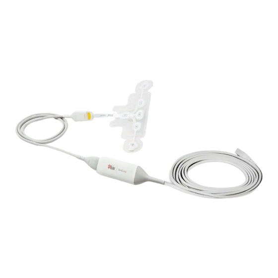
Page 18: Sedline Module
Cable and receives its power from Root. SedLine Patient Cable The SedLine Patient Cable transfers analog EEG signals collected from the SedLine Sensor to the SedLine Module for processing. The patient cable is reusable and may be used from patient to patient. www.masimo.com... -
Page 19: Sedline Sensor(S)
Chapter 2: System Descriptions SedLine Sensor(s) The SedLine Sensor is comprised of six (6) gelled electrodes, including four (4) active channels (R1, R2, L1, L2), one reference channel (CT), and one ground channel (CB). The sensor is a single-use, non-sterile product that does not contain natural rubber latex. -
Page 21: Chapter 3: Setting Up The System
Check all materials against the packing list. Save all packing materials, invoice and bill of lading. These may be required to process a claim with the carrier. If anything is missing or damaged, contact Masimo Technical Service. Preparation for Use... -
Page 22: Connecting The Module To Root
Push to insert. For additional details, see the Directions for Use (DFU) for the patient cable. Connecting the Module to Root To connect the module to Root Identify the Masimo Open Connect (MOC-9 ) end of the module. www.masimo.com Masimo... -
Page 23: Connecting The Sedline Sensor To The Patient
Insert the MOC-9 end of the module securely into a MOC-9 port on Root. Connecting the SedLine Sensor to the Patient For directions on how to connect the SedLine Sensor, see the Directions for Use (DFU) for SedLine Sensors. www.masimo.com... -
Page 25: Chapter 4: Operation
Chapter 4: Operation The following sections describe how SedLine information is displayed when used with Root, including display details and accessing and changing user-configurable settings. For additional information, see Operator's Manual for Root. The SedLine Window When SedLine is connected to Root, parameters and measurements display in a window. -
Page 26: Eeg Display
EEG Chart Speed cannot be changed. Refer to the Operator's Manual for Root. Electrode Status This feature in the SedLine window is used to monitor electrode impedance. To reveal the Electrode Status Display, swipe down on the tab shown below. - Page 27 For example, the Electrode Status display icon labeled as R2 corresponds to the R2 electrode of the sensor. Each icon label corresponds with electrode label on SedLine Sensor Each individual electrode status is composed of three components: L/R/CB (Left/Right/Center) represents the corresponding sensor electrodes.
-
Page 28: Parameters Display
SedLine Sedation Monitor Chapter 4: Operation Icon Color Example Description Green Electrode impedance is in good range and acceptable. Yellow Electrode impedance is marginal but acceptable. Electrode impedance is out of acceptable range. Electrode impedance is extremely high or disconnection of Blue sensor electrodes. - Page 29 SedLine Sedation Monitor Chapter 4: Operation Numeric Value PSi is represented by a numeric value that ranges from 0 to 100. When a PSi numeric value is not available, the value displays dashes (--). The PSi value displays in conjunction with two smaller numeric values, the high alarm limit and low alarm limit.
- Page 30 SedLine (requires firmware 2010 or higher). Note: With Root software version v1.8.1.4 or higher, the default setting is Multitaper. To access the Multitaper version of SedLine: Access the SedLine option from the main menu. Select parameter settings. Select Density Spectral Array (DSA).
- Page 31 SedLine Sedation Monitor Chapter 4: Operation Asymmetry Graph The Asymmetry Graph quantifies the difference in the brain activity between the left and the right sides with an asymmetry measurement, ASYM, displayed to the right of the graph. An ASYM value of zero implies that the left and right hemispheres have the same level of activity.
- Page 32 SedLine Sedation Monitor Chapter 4: Operation ARTF (Artifact) Artifact (ARTF) is a measure of how much physiological (non-brain related) and environmental noise the system detects. Numeric Value ARTF is represented by a numeric value that ranges from 0 to 100%. When an ARTF numeric value is not available, the value displays dashes (--).
-
Page 33: View Options
View Options When SedLine is the only MOC-9 technology connected to Root, the SedLine window will display in full as shown in the following image. To change the view in the SedLine window, toggle between the Trend and Analog tabs. - Page 34 SedLine Sedation Monitor Chapter 4: Operation The Parameters Display can be customized by expanding and minimizing the parameters and measurements in both Trend View and Analog View. Each parameter can be minimized to display only its Numeric Value and Parameter Label. To minimize a parameter's Trend Display, press and hold its Numeric Value until it dims, then drag-and-drop it into the Well.
- Page 35 SedLine Sedation Monitor Chapter 4: Operation The second image shows the customized view after ARTF, SEFL and SEFR are expanded and PSi is minimized. www.masimo.com Masimo...
- Page 36 When multiple MOC-9 technologies are connected, the user will have the option to select one of several pre-configured layouts for optimal viewing. Shown in the following illustration is the SedLine window at 37.5% of the display. 1 View Options: Trend, EEG, DSA, Analog 2 Action Menu To select a viewing option, press the action menu icon and press Trend, EEG, DSA, or Analog icons.
-
Page 37: Chapter 5: Menu Options
SEFL, SEFR, EMG, SR, and ARTF. To access a specific parameter's configuration settings • Press the parameter desired directly from the SedLine window. To access all parameter configuration settings Press the Main Menu icon at the bottom right corner of the screen to access menu options. - Page 38 On or Off Alarms* * SedLine has the ability to control alarm priority based on the clinical use case. When Audible Alarms are set to Off, the alarm priority is Low. When Audible Alarms are set to On, the alarm priority is Medium.
- Page 39 SedLine Sedation Monitor Chapter 5: Menu Options Trends Factory Options Description Selectable Settings Default Y-Axis Upper limit of power 15 dB -40 to 40 dB in 5 dB increments spectrum Y-Axis Min Lower limit of power -60 to -20 dB in 5 dB...
- Page 40 Standard Sensitivity detection. Maximum * Available on SedLine with software V232x or higher. About An informational read-only screen with definition of SR: Suppression Ratio (SR) is a measure of how much the electrical activity of the frontal and pre-frontal cortex of the brain is suppressed.
- Page 41 SedLine Sedation Monitor Chapter 5: Menu Options Factory Options Description Selectable Settings Default Y-Axis Highest SR value that can be 5% to 100% in 5% 100% displayed increments Y-Axis Lowest SR value that can be 0% to 95% in 5 %...
-
Page 42: Additional Settings
0 Hz to 25 Hz in 5 Hz 0 Hz be displayed increments Additional Settings SedLine Additional Settings provide the user access to EEG and DSA settings as well as SedLine Sensor information. Use the Additional Settings screen to configure the following: Factory Options... -
Page 43: Chapter 6: Eeg Download
EEG waveforms displayed into sessions. Terminate the recording session by disabling Data Collection in the Access Control menu. Root will record up to 12 continuous hours of EEG waveforms per session. When recording exceeds 12 sessions, the oldest session will be erased as the newest session starts recording. www.masimo.com Masimo... -
Page 44: Download Eeg Waveforms
SedLine Sedation Monitor Chapter 6: EEG Download Download EEG Waveforms To download the EEG waveforms onto the USB stick: Ensure that there is a folder titled, “edf”, in the USB stick that is used to download EEG waveforms from Root. Without this folder, the download cannot activate. -
Page 45: Chapter 7: Alarms And Messages
Chapter 7: Alarms and Messages Messages and Indications The table below lists the types of messages that can appear on Root when using SedLine. Error Message Indication SedLine is Indicates that the SedLine module is not connected. Disconnected No Sensor... -
Page 47: Chapter 8: Troubleshooting
Chapter 8: Troubleshooting Troubleshooting SedLine To troubleshoot issues with Root, see the Operator's Manual for Root. To troubleshoot issues with the Masimo sensor, see the Directions for Use (DFU) for the sensor. If a problem persists, contact an Authorized Masimo Representative. Message... -
Page 48: Adjusting Electrodes
If a signal is noisy or high in amplitude and appears different from the other channels. To improve electrode contact Note: After making any electrode adjustments, wait two (2) to three (3) seconds for SedLine to update. It is important to check the electrodes in the order listed below: Icon Color... -
Page 49: Trends Not Available
SedLine Sedation Monitor Chapter 8: Troubleshooting Icon Color Action Ensure that the sensor connection with the patient cable is Blue secure. Gently push/wiggle electrodes until all are yellow and/or green. The Sensor may need to be replaced. Dark Gray with... - Page 50 The following information may help resolve line power and high frequency artifact issues. Issue Action Confirm that all displayed parameters are Proximity of the SedLine Module to within normal limits. other devices can cause high Change the location of Root and plug it frequency interference.
-
Page 51: Chapter 9: Specifications
DSA Amplitude (Left and Right) -60 dB to 40 dB DSA Asymmetry -100% to +100% Electrode Impedance 0 Ohms to 65 KOhms Resolution Parameter Resolution ARTF SEFL/SEFR 1 Hz DSA Amplitude (Left and Right) ≤1 dB DSA Asymmetry Electrode Impedance ≤ 1 KOhm www.masimo.com Masimo... -
Page 52: Environmental
Retrospective Assessment of PSi by Independent EEG Experts Study Type Retrospective Study The study compared the performance of two SedLine Patient State Index Study Design (PSi) algorithms (proposed vs. predicate) through a review by three independent EEG experts, Board Certified Anesthesiologists. -
Page 53: Safety Classifications
SedLine Sedation Monitor Chapter 9: Specifications Expert Review Analysis of overall data Old PSi V1031 New PSi V2000 Success rate Success rate Overall GABA with NMDA Safety Classifications Equipment Classification per IEC 60601-1 Type of Protection Class II Degree of Protection of Electrical Shock... -
Page 54: Emc Compliance
SedLine Sedation Monitor Chapter 9: Specifications EMC Compliance EMC Compliance See Operator's Manual for Root. Symbols The following symbols may appear on the product or product labeling: Symbol Description Symbol Description Follow instructions for use Consult instructions for use ETL Intertek certification... - Page 55 SedLine Sedation Monitor Chapter 9: Specifications Symbol Description Symbol Description Electrostatic Biohazardous Waste Not for continuous monitoring No parameter alarms (No alarm for SpO Product contains no PVC Caution (polyvinyl chloride) material Not made with natural rubber Manufacturer latex Date of manufacture...
- Page 56 SedLine Sedation Monitor Chapter 9: Specifications Symbol Description Symbol Description Wireless features can be used in member states with the Stand-By restriction of indoor use in France -Class 2 wireless device RS-232 Interface Iris Connection Analog Out Interface Ethernet Greater than...
-
Page 57: Chapter 10: Service And Maintenance
Chapter 10: Service and Maintenance Cleaning Procedures Cleaning of SedLine should be performed at regular intervals in accordance with hospital, as well as local and governmental regulations. See Safety Information, Warnings and Cautions on page 9. SedLine is a reusable instrument. The instrument is supplied non-sterile. -
Page 58: Repair Policy
Cleaning Procedures on page 55. Make sure the equipment is fully dry before packing. To return SedLine for service, please follow the Return Procedure on page 56. Return Procedure Please clean contaminated/dirty equipment before returning and make sure it is fully dry before packing the equipment. -
Page 59: Contacting Masimo
Masimo for a full refund. Warranty Masimo warrants to the initial Purchaser for a period of one (1) year from the date of purchase that: each new Product and the Software media as delivered are free from defects in workmanship or materials. - Page 60 Products or Software. In no event shall Masimo’s liability arising from any Product and Software (under contract, warranty, tort, strict liability or other claim) exceed the amount paid by purchaser for the Products giving rise to such claim.
- Page 61 SedLine Sedation Monitor Chapter 10: Service and Maintenance be prohibited except to the extent expressly permitted by the terms of this Agreement. No Implied License Possession or purchase of this device does not convey any express or implied license to use the device with unauthorized Sensors or cables that would, alone, or in combination with the device, fall within the scope of one or more of the patents relating thereto.
-
Page 63: Index
Connecting the Module to Root • 20 Index Connecting the Module to the Patient Cable • 19 Connecting the SedLine Sensor to the Patient • 21 About This Manual • 5 Contacting Masimo • 56, 57 Additional Settings • 24, 40 Contraindications •... - Page 64 SedLine Sedation Monitor Index SedLine Module Physical Characteristics • 50 Line Power and High Frequency Artifacts SedLine Patient Cable • 16 • 48 SedLine Sensor(s) • 17 SEFL and SEFR • 39 SEFL and SEFR (Spectral Edge Messages and Indications • 43 Frequencies) •...
- Page 66 35548/LAB-7373G-0619...
Need help?
Do you have a question about the SedLine and is the answer not in the manual?
Questions and answers
How do I solve error moc 9 port #3