Table of Contents
Advertisement
Quick Links
12 MRX, 15 MRX, 12 MY-H, 12 HLX,
15 HLX, 15 MY-H, 16 MY-H, 18 MY-H
AGROMEHANIKA reserves the right to design modifications or product changes, without any liabilities to inform the
TRAILED TRACTOR SPRAYER
AGS 1800 EN-HV
AGS 2000 EN-HV
AGS 2000 EN-HVB
AND SPRAYING BOOMS
INSTRUCTIONS FOR USE
customer before and after each change.
Rev. 09/2018
Advertisement
Table of Contents

Subscribe to Our Youtube Channel
Related Manuals for Agromehanika AGS 1800 EN-HV


Summary of Contents for Agromehanika AGS 1800 EN-HV
- Page 1 12 MRX, 15 MRX, 12 MY-H, 12 HLX, 15 HLX, 15 MY-H, 16 MY-H, 18 MY-H INSTRUCTIONS FOR USE AGROMEHANIKA reserves the right to design modifications or product changes, without any liabilities to inform the customer before and after each change.
- Page 2 INSTRUCTIONS FOR USE AGS 1800 - 2000 EN-HV (HVB) Rev.9/2018...
-
Page 3: Table Of Contents
INSTRUCTIONS FOR USE INDEX: GENERAL ....................10 HEALTHY-SAFETY WARNINGS AND MEASURES ......11 SAFETY SIGNS ..................11 MAINTENANCE OF SAFETY SIGNS ............. 11 READINESS FOR DANGER ..............11 REMOVING UNAUTHORIZED PERSONS ..........11 SAFETY IN HANDLING WITH CHEMICAL PRODUCTS ....12 LABELS FOR DANGER, ACCORDING TO DANGER LEVEL .... - Page 4 INSTRUCTIONS FOR USE CHASSIS OF THE SPRAYER AND ADJUSTABLE WHEEL TRACK . 33 MAIN RESERVOIR ..................34 RESERVOIR FOR RINSING ..............35 RESERVOIR FOR WASHING HANDS ............ 35 MIXING NOZZLE ..................36 SUCTION FILTER ..................36 7.6.1 CLEANING FILTER INSERT ..............36 NOZZLE FOR CLEANING INTERIOR OF MAIN RESERVOIR ...
- Page 5 INSTRUCTIONS FOR USE 11 GUIDES FOR AGS 1800 EN-HV, 2000 EN-HV AND 2000 EN-HVB SPRAYERS ....................52 11.1.1 HYDRAULIC LIFTING MECHANISM ........... 52 11.1.2 ADJUSTABLE HEIGHT ................52 11.1.3 EXTENSION FOR MRX BOOMS ............53 11.1.1 HYDRAULIC SHOCK ABSORBERS ON THE SPRAY BOOm .... 54 12 SPRAYING EQUIPMENT 15 MY-H, 16 MY-H IN 18 MY-H .....
- Page 6 INSTRUCTIONS FOR USE 13.3 TRANSPORT SAFETIES ................82 13.3.1 MECHANICAL SHOULDER SUPPORTS FOR THE BOOM ARM ..82 13.3.2 MECHANICAL SAFETIES AGAINST OPENING OF BOOMS IN TRANSPORT POSITION ....................83 13.3.3 SAFETY AGAINST OPENING AND CLOSING OF BOOMS ....83 13.4 CHARACTERISTICS OF SPRAYING EQUIPMENT 12 HLX IN 15 HLX84 13.4.1 HYDRAULIC BLOCKAGE AND DAMPENING ........
- Page 7 INSTRUCTIONS FOR USE 16.5 CLEANING THE SPRAYING DEVICE ..........111 16.6 MAINTENANCE AND STORAGE AFTER SEASON ......112 16.6.1 HOSES ...................... 112 16.6.2 PAINT ....................... 112 16.6.3 RESERVOIR .................... 112 16.6.4 PRESSURE REGULATOR ..............112 16.6.5 PUMP......................113 16.6.6 DRIVE/CARDAN SHAFT ..............113 16.6.7 BOLTS ......................
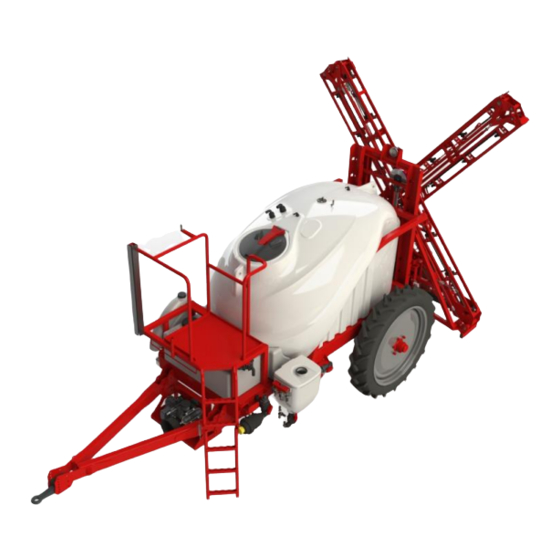
- Page 8 INSTRUCTIONS FOR USE SPRAYER AGS 2000 EN-HV WITH 15 HLX SPRAY BOOM AGS 1800 - 2000 EN-HV (HVB) Rev.9/2018...
- Page 9 INSTRUCTIONS FOR USE EC DECLARATION OF CONFORMITY MANUFACTURER: AGROMEHANIKA, proizvodnja in trgovina Kranj d.d. Hrastje 52 a, KRANJ, SLOVENIJA declares that the product: SPRAYER AGS 1800 EN-HV SPRAYER AGS 2000 EN-HV SPRAYER AGS 2000 EN-HVB is manufactured in accordance with: 1.
- Page 10 INSTRUCTIONS FOR USE ACKNOWLEDGEMENT We thank you for the trust, given when choosing our spraying device AGROMEHANIKA for chemical protection of plants. Reliability and performance of the device depends on your care for the device. Before connecting the spraying device to a tractor carefully read the instructions for use and heed to them, while operating the machine.
-
Page 11: General
INSTRUCTIONS FOR USE 1 GENERAL Spraying device is designed and constructed for applying chemical products in water-based solution, which are normally used for chemical protection of crops, on field crops. Construction design enables access to all vital elements of the sprayer and easy handling. Robust construction, quality component parts and a great deal of additional equipment enable the user to work reliably and use spraying agents and energy optimally. -
Page 12: Healthy-Safety Warnings And Measures
INSTRUCTIONS FOR USE 2 HEALTHY-SAFETY WARNINGS AND MEASURES 2.1 SAFETY SIGNS Sign on the left is a warning safety sign and is normally located on the machine with other signs. Respect instructions for safe work and act accordingly in extreme situations. 2.2 MAINTENANCE OF SAFETY SIGNS Carefully read instructions, regarding safety regulations, described in instructions for use of your machine. -
Page 13: Safety In Handling With Chemical Products
INSTRUCTIONS FOR USE WARNING: Driving unauthorized persons on the machine is prohibited! 2.5 SAFETY IN HANDLING WITH CHEMICAL PRODUCTS Handle chemical products extremely carefully, to avoid potential injuries and dangers to health, as well as to the environment: • Be very careful, when handling chemical products. Ensure that you do not have direct contact with chemical products. -
Page 14: Labels For Danger, According To Danger Level
INSTRUCTIONS FOR USE • Clean and wash the machine after each use and before each maintenance procedure. If you have any health issues while dealing with chemical products, consult your physician and • try to contact the dealer of the chemical product. If you have had an accident with a chemical product, we propose the following safety •... -
Page 15: Danger Of Mechanical Injuries
INSTRUCTIONS FOR USE 2.7 DANGER OF MECHANICAL INJURIES • do not touch the machine while operating; • do not remove safety labels or any other safety equipment of the machine; • do not exceed air pressure in the tyres; • maintain the tyres regularly; •... -
Page 16: Personal Protection
INSTRUCTIONS FOR USE • While spraying keep the windows and doors of the tractor closed. It is recommended that the operator has a hermetically closed cabin which allows the operator to create overpressure with aeration of fresh air that disables chemically polluted air to enter the cabin. •... -
Page 17: Skin Protection
INSTRUCTIONS FOR USE • Write down the date of the last usage of the filter. The A2P2 filter must be replaced once a month nevertheless how many times it was used. Filter B must be replaced after every single use! The filter must be used within 6 months after the packaging of the filter was opened. Make sure that used filters are destroyed in accordance with local regulations. -
Page 18: Safe Maintenance
INSTRUCTIONS FOR USE • Never bring personal things in the area of spraying or when handling chemicals. Before every meal thoroughly clean your hands and face and wash out your mouth with fresh water. • Before using chemicals, check machine operation with clean water. •... -
Page 19: Road Transport
• Observe the local traffic code when driving on public roads. • The sprayer must be equipped with road safety equipment. • Agromehanika, d.d. provides the sprayer with equipment, complying with the Regulation EU no. 167/2013, and type approval. 2.17 PROCEDURES IN ACCIDENTS WITH CHEMICALS If your skin or eyes come in contact with chemicals or their solution, wash them out with plenty of water and repeat the process several times. -
Page 20: Safety Signs On Machine And Instructions For Use19
INSTRUCTIONS FOR USE 3 SAFETY SIGNS ON MACHINE AND INSTRUCTIONS FOR USE Machine and instructions for use contain safety and warning signs. Take a closer look to ensure your safety. Follow instructions and guidelines, referring to safety measures, given in the previous chapter. Ensure that the safety signs are well visible. - Page 21 INSTRUCTIONS FOR USE Warning: CE declaration of conformity presence of poisonous chemical products! Warning: symbol, indicating Warning: possibility of personal injury or maximal allowed pressure in the damage of the machine! spraying device (12 bar)! Warning: keep away from Warning: rotating drive shafts! direction of cardan shaft rotation.
-
Page 22: Description
INSTRUCTIONS FOR USE 4 DESCRIPTION The sprayers type AGS 1800 EN-HV, AGS 2000 EN-HV and AGS 2000 EN-HVB feature a modern design with a polyethylene tank resistant to chemicals, with rounded edges, smooth interior walls a sloping bottom. The structure of the sprayer ensures excellent balance, simple use, good mixing of the spray, complete emptying of the reservoir and easy cleaning. - Page 23 INSTRUCTIONS FOR USE Figure 4.2 The bottom of the chassis must not be used for lifting the sprayer (when using a forklift) because of the tubing, valves and protections which are installed under the reservoir. Figure 4.3 AGS 1800 - 2000 EN-HV (HVB) Rev.9/2018...
-
Page 24: Sprayer Component Parts
INSTRUCTIONS FOR USE 4.2 SPRAYER COMPONENT PARTS Figure 4.4 AGS 1800 - 2000 EN-HV (HVB) Rev.9/2018... - Page 25 INSTRUCTIONS FOR USE AGS 1800 - 2000 EN-HV (HVB) Rev.9/2018...
-
Page 26: Machine Identification
INSTRUCTIONS FOR USE 4.3 MACHINE IDENTIFICATION 4.3.1 MACHINE IDENTIFICATION PLATE Attached to the front side of the sprayers and contains following important information: • name address machine manufacturer, • product type, • model, • capacity (size), • empty machine weight, •... -
Page 27: Approval Plate
INSTRUCTIONS FOR USE When ordering spare parts, all of the information written on the identification plate must be given to the seller. 4.3.1 APPROVAL PLATE This plate contains all the information on the approval. • Manufacturer’s name • Vehicle type •... -
Page 28: Function Scheme
INSTRUCTIONS FOR USE 4.4 FUNCTION SCHEME Figure 4.5 AGS 1800 - 2000 EN-HV (HVB) Rev.9/2018... -
Page 29: Additional Equipment
INSTRUCTIONS FOR USE Legend: 1. Main reservoir 13. Selector valve an main reservoir drain 14. Selector valve for the main or additional 2. Additional reservoir reservoir 3. Piston diaphragm pump 15. Suction basket 4. Centrifugal pump 16. T-distributor piece 5. Pressure line valve 17. -
Page 30: Conection Sprayer To Tractor
INSTRUCTIONS FOR USE 5 CONECTION SPRAYER TO TRACTOR The AGS 1800EN-HV, AGS 2000EN-HV and AGS 2000EN-HVB sprayers were designed to be attached to the lower tractor linkage (towing eyes with a diameter of 40 mm and 50 mm are interchangeable). The height of the rigid or the swivel hitch can be adjusted, which means that the sprayer can be attached to different tractors. - Page 31 INSTRUCTIONS FOR USE LEGEND: 1. support leg, 2. lever for the support leg, 3. safety bolt, 4. pin, 5. bottom safety bolt, 6. bottom pin Figure 5.2 AGS 1800 - 2000 EN-HV (HVB) Rev.9/2018...
-
Page 32: Drive - Cardan Shaft (Not Included)
INSTRUCTIONS FOR USE 6 DRIVE - CARDAN SHAFT (NOT INCLUDED) 6.1 OPERATOR'S SAFETY WARNING: To avoid accidents and personal injuries, follow these recommendations and safety regulations! • Before mounting (connecting of the cardan shaft to the tractor and the sprayer) the drive shaft – cardan shaft, always turn off the engine and remove the start key from its lock. - Page 33 INSTRUCTIONS FOR USE 6. Attach profiles and connect both parts of the cardan shaft. 7. Mount the cardan shaft between the tractor and the sprayer. 8. To ensure a long reliability of the cardan shaft, avoid angles larger than 15°. 9.
-
Page 34: Detailed Description With Instructions For Work
INSTRUCTIONS FOR USE 7 DETAILED DESCRIPTION WITH INSTRUCTIONS FOR WORK The sprayer's chassis consists of a welded steel structure that holds the tank. The front part contains the piston diaphragm pump, the centrifugal pump, the pressure filter, litre scale and a regulator for controlling the sprayer. - Page 35 INSTRUCTIONS FOR USE Figure 7.2 7.2 MAIN RESERVOIR The main reservoir is made of polyethylene which is resistant to chemicals. It has rounded edges and smooth inner walls for easier cleaning. The reservoir has a sloping bottom which assures a complete emptying of it.
- Page 36 INSTRUCTIONS FOR USE Figure 7.3 7.3 RESERVOIR FOR RINSING The reservoir for rinsing is intended for washing of the reservoir and other elements after you have finished working or after a break. Fill the reservoir with clean water. You can find more detailed instructions in the chapter "DESCRIPTION OF SETTING OF VALVES FOR SPRAYING OR CLEANING".
- Page 37 INSTRUCTIONS FOR USE 7.5 MIXING NOZZLE To ensure better mixing, the sprayer is fitted with mixing nozzles, integrated into the bottom part of the reservoir. The mixing nozzles are supplied directly by the centrifugal pump C200. Mixing is always activated when the PTO drive shaft on the tractor is engaged.
- Page 38 INSTRUCTIONS FOR USE 7.7 NOZZLE FOR CLEANING INTERIOR OF MAIN RESERVOIR Nozzle is mounted in the interior of main reservoir and is intended for washing of reservoir's interior after finished spraying. It is connected to one of the supply valves on pressure regulator, which, when open, provides required water for cleaning.
- Page 39 INSTRUCTIONS FOR USE Figure 7.9 7.8.1 FILLING CONTAINER OPERATION Fill the main reservoir to about 1/3 with water, turn on the pump, then open the main valve on pressure line and fill approximately 1/10 of the filling container with water by opening the control valve (7) which supplies the filling container.
- Page 40 INSTRUCTIONS FOR USE 7.9 PACKAGING RINSING NOZZLE Figure 7.10 The valve is designed to wash the packaging of liquid plant protection chemicals. It is installed inside the filling container and connected with the valve on the filling container (8) through a hose. The packaging is washed by placing it over the nozzle (9) and administering water through the valve (8).
- Page 41 INSTRUCTIONS FOR USE Figure 7.11 The valve flow direction is marked with an arrow on the lever of the valve. Proper adjustment of the spraying valves is shown in Figure 7.11. Turn the three-way valve for excess liquid (4 – Figure 4.5) so that the excess spray is directed back into the main tank (Figure 7.12).
- Page 42 INSTRUCTIONS FOR USE When performing the complete cleaning of the sprayer, it is recommended to also clean the filling container (17 – Figure 4.5). Open the selector valve (5 – Figure 4.5) for the filling container and activate the valve on the container to use the packaging cleaner (8 – Figure 7.7). After cleaning, close the valve and pump the water back into the reservoir using the ejector nozzle (20 –...
- Page 43 INSTRUCTIONS FOR USE 8 ADDITIONAL EQUIPMENT 8.1 SET FOR EXTERIOR WASHING OF SPRAYING DEVICE After finished working the spraying appliance needs to be cleaned. The most appropriate place for cleaning is at the edge of the surface where you have had just finished operating the machine. For this purpose, a set for outer cleaning of the spraying appliance is a big help.
- Page 44 INSTRUCTIONS FOR USE Figure 8.2 WARNING: Be very careful when sucking water out of a pond, since a small inattention can poison the water in it! AGS 1800 - 2000 EN-HV (HVB) Rev.9/2018...
- Page 45 INSTRUCTIONS FOR USE 9 PRESSURE REGULATOR 9.1 PRESSURE REGULATOR COMPONENTS Central regulation system Self-cleaning pressure filter Directional control valve Manual or electric motor operated section valves Pressure gauge Control panel (electric control box) Figure 9.1 9.1.1 REGULATOR MARKING Basic marking of regulator is 10EC. Basic marking has an added: −...
- Page 46 INSTRUCTIONS FOR USE Main valve Regulation electric motor valve 3. Maximum operating pressure adjustment Figure 9.9.2 9.1.3 SELF-CLEANING FILTER The self-cleaning pressure filter additionally cleans the insecticide before this is sprayed through the nozzles. Small parts that get caught in the filter insert (density M 50) are sent back to the reservoir through the valve mounted at the bottom of the filter (A) when cleaning the filter insert.
- Page 47 INSTRUCTIONS FOR USE 9.1.4 DIRECTIONAL CONTROL VALVE EC (ARAG) The EC directional control valve (ARAG) with an integrated electric motor is used to open and close the flow in individual sections of the spray boom (On/Off valve) (B). When this valve is closed, the return valve (A) opens to adjust the amount of water returning into the reservoir.
- Page 48 Figure 9.6 control box) 9.4 PR3 ECEFM (AG-TRONIK) PRESSURE REGULATOR This pressure regulator by Agromehanika d.d. is equipped with the AG-TRONIK computer, which is accompanied by all the corresponding instructions for use. 9.5 PRESSURE REGULATOR MAINTENANCE After every single spraying the regulator needs to be washed with clean water. This is done by letting clean water flow through the regulator (see chapter "COMPLETE CLEANING OF THE...
- Page 49 INSTRUCTIONS FOR USE 10 PUMPS Pumps are a vital element of spraying appliances. The reliability and a long durability of the pump also depend on how you treat the pump and whether you use and maintain it correctly. IMPORTANT: The standard version of all pumps is equipped with membranes which are made of NBR rubber.
- Page 50 INSTRUCTIONS FOR USE 10.2 USE Before turning on the pump, make sure that the main valve on pressure regulator is closed (return to reservoir. Never turn on the pump’s drive when the setting on the regulator enables full load on the pump. Turn on the pump and let it run for approximately one minute under minimum pressure in order to aerate the pump and the inlet and the outlet pipes.
- Page 51 INSTRUCTIONS FOR USE WARNING: The machine IS NOT SUITABLE FOR LIQUID FERTILIZERS! If you intend to make an exception, we recommend that you consult the technical service department! OPERATION INTERVAL CHECKS Every 8 h Every 50 h Every 300 h 1x per season Oil level check Air chamber check...
- Page 52 INSTRUCTIONS FOR USE possible to recognise a damaged membrane by means of the manometer, since its pressure pointer does not come to a halt. 10.4.5 MAINTENANCE After every single use, it is recommended to wash out the inside of the pump as well as other parts of the sprayer with clean water (see chapter "DESCRIPTION OF SETTING OF VALVES FOR SPRAYING OR CLEANING"), and after season, the pump must be prepared for winter (see chapter "MAINTENANCE AND STORAGE AFTER SEASON –...
- Page 53 INSTRUCTIONS FOR USE 11 GUIDES FOR AGS 1800 EN-HV, 2000 EN-HV AND 2000 EN-HVB SPRAYERS 11.1.1 HYDRAULIC LIFTING MECHANISM The hydraulic lifting mechanism is the same for all spray booms. The hydraulic lift cylinder is a single-action type. A double locking valve (1) ensures safety by preventing the spray boom from dropping suddenly if the hose is broken.
- Page 54 INSTRUCTIONS FOR USE in the third position. This is the basic height for the booms, which ensures that the nozzles are 50 cm above ground when the hydraulic cylinder is in the lowest position. It is also possible to spray crops up to a height of 204 cm (high crops) by using the fifth (highest) position.
- Page 55 INSTRUCTIONS FOR USE 11.1.1 HYDRAULIC SHOCK ABSORBERS ON THE SPRAY BOOM The hydraulic accumulator connected to the lift cylinder acts like a vertical shock absorber. It is located on the guides of the sprayer. The accumulator dampens the jolts, thereby reducing the stress on the spray boom.
- Page 56 INSTRUCTIONS FOR USE 12 SPRAYING EQUIPMENT 15 MY-H, 16 MY-H IN 18 MY-H The 15 MY-H, 16MY-H and 18 MY-H spray booms are hydraulically foldable. Opening and closing from the transportation position into working position and vice-versa is performed with the help of hydraulic cylinders, which enable individual opening or closing of spraying booms.
- Page 57 INSTRUCTIONS FOR USE 12.2 COMPONENTS FOR CONTROLLING SPRAYING EQUIPMENT 12.2.1 CONTROL PANEL Control panel is a component part of controlling hydraulics of spraying equipment 15MY-H, 16MY-H and 18MY-H, and must be installed in an appropriate place in the tractor cabin. It contains graphic display of all working functions, which can be performed with hydraulics.
- Page 58 INSTRUCTIONS FOR USE 12.2.2 CONNECTION OF SPRAYING EQUIPMENT TO TRACTOR 12.2.2.1 CONNECTION ELECTRIC CABLES Connection cable between control panel and solenoid hydraulic valves Supply cable + supply plug Figure 12.3 Technical and working characteristics: Description Value Supply voltage 12V DC 0°C - 70°C Working area Fuse...
- Page 59 INSTRUCTIONS FOR USE To avoid incorrect connection of hydraulic hoses of spraying equipment with tractor hydraulics and improper operation in controlling the spraying equipment, the hoses are marked with a label for correct connection: • unmarked hose pair: connection to the hydraulic cylinder to control the lifting/lowering of the spray boom (see chapter 11.1.1.1) •...
- Page 60 INSTRUCTIONS FOR USE Figure 12.5 12.2.3 WIRING DIAGRAM 15 MY-H, 16 MY-H, 18 MY-H 12.2.3.1 MEANING OF MARKINGS IN THE WIRING DIAGRAM Marking Description Note Control panel for control of equipment Connection hydraulic hoses with clamps for connection to tractor Connection cable between control panel, hydraulic valves and block Supply cable + supply plug Hydraulic couplings on the tractor...
- Page 61 INSTRUCTIONS FOR USE Hydraulic multi-port solenoid valve 2/2, double Multi-port solenoid valve 2/2 EV 1-4 Solenoid coil Two hydraulic supply connections on the tractor with a yellow P1, P2 marking P3, P4 Two hydraulic supply connections for hydraulic lifting, no marking 12.3 TRANSPORT SAFETIES Spraying equipment is fitted with mechanical safety, which prevents uncontrolled opening of side booms in transport position.
- Page 62 INSTRUCTIONS FOR USE Figure 12.7 WARNING: Incorrectly folded spraying equipment to transport position does not ensure safety from uncontrolled opening of booms during transport! 12.3.3 SAFETY AGAINST OPENING AND CLOSING OF BOOMS Spraying equipment is equipped with a system, which disables opening or closing of booms in working height of spraying equipment.
- Page 63 INSTRUCTIONS FOR USE Main component parts of spraying equipment are: • guide AGS, • shoulder carrier, • shoulders, • oscillating lever, • boom 1-L, • boom 1-D, • boom 2-L, • boom 2-D, • pivot joint 3-L, • pivot joint 3-D, •...
- Page 64 INSTRUCTIONS FOR USE Figure 12.10 Height setting of equipment is done with screw (1) on the top of the eye bearing (Figure 12.9), and perpendicularity between spraying equipment and sprayer in ensured by polyurethane springs (2), which must be equally set or pre-strained (Figure 12.9) to ensure, in case of lateral inclination of spraying equipment, its positioning in original position (Figure 12.11).
- Page 65 INSTRUCTIONS FOR USE Figure 12.12 Figure 12.13 Legend for Figure 12.12 and Figure 12.13: 1. Hydraulic cylinder of block and damper 2. Damper for setting response of damping 3. Solenoid valve 4. Oscillating lever of spraying equipment 5. Shoulder carrier (cart) 6.
- Page 66 INSTRUCTIONS FOR USE Figure 12.14 12.4.2.2 PROCEDURE OF FILLING OF HYDRAULIC CYLINDER • Before connecting the cylinder, all connections for hydraulic hoses must be facing upwards, due to air displacement during filling. • Connect hydraulic hoses P1 and P2 to cylinder connections. Figure 12.15 •...
- Page 67 INSTRUCTIONS FOR USE o At uninterrupted filling, after certain still time of piston in end point due to aeration, divert oil flow on the device in the opposite direction and repeat filling, done in reverse order. o Repeat the filling procedure until airless space in the cylinder is ensured. o Piston in the cylinder moves with steady response, set through the damper.
- Page 68 INSTRUCTIONS FOR USE WARNING: Activated block is not intended for normal work, but is intended only for opening and closing of spraying equipment and in case of spraying with partially one-side closed booms! In case of spraying with partially one-side closed booms, tractor speed must be reduced accordingly, to prevent overturning and damage to sprayer and spraying equipment.
- Page 69 INSTRUCTIONS FOR USE Legend of figures 12.18 and 12.19: 1. Blocking mechanism with a damper 2. Double hydraulic solenoid valve 2/2 3. Oscillating lever of the spray boom 4. Hydraulic solenoid valve 6/2 5. Levelling cylinder 6. Flow control valve Figure 12.19 12.4.4 ADJUSTABLE GUIDES Adjustable...
- Page 70 INSTRUCTIONS FOR USE Guides, which slide on the interior side of frame (Figure 12.21), are set by an adjustable screw (1). Partially unscrew the screws (3), which are fixing the guide. Setting is done with adjustable screw (1) until guide does not reach minimum airiness.
- Page 71 INSTRUCTIONS FOR USE Rear boom (third boom) is fastened, through adjustable screw, in single point in top part, and elastically with spring in the bottom part, which enables movement of boom left, right and up. In case of an obstacle or contact with the ground, boom moves away and returns to original position. 1.
- Page 72 INSTRUCTIONS FOR USE Figure 12.26 12.4.7 BOOM OPENING MECHANISM Mechanism for opening first boom is done directly through hydraulic cylinder (1) (Figure 12.27), fastened to shoulder and first boom. Parallelism and rigidness of first boom with spraying equipment are ensure by tensioning pole (2), which also connects the second boom through link lever (2). Figure 12.28 Figure 12.27 Adjustable screw (4) between joint part ensures that booms 1 and 2 are in parallel position.
- Page 73 INSTRUCTIONS FOR USE The third arm is opened with the hydraulic valve (5) (Figure 12.30), which lowers the arms 1 and 2 and activates the other cylinder (6) (Figure 12.31) connected to the mechanism through the lever (7) and the safety hinge (8). Figure 12.31 Figure 12.30 Two adjustable screws (9, 10) on safety joint and between joint part ensure parallelism and parallel...
- Page 74 INSTRUCTIONS FOR USE 12.4.7.1 HYDRAULIC CYLINDERS FOR CONTROL OF BOOMS For final setting of both hydraulic cylinders with booms of spraying equipment, both have a nut (1) and end fitting (2) at the hitching part. Nut enables the cylinder to limit position of closing of booms, end fitting on hydraulic cylinder enables end position of opened equipment.
- Page 75 INSTRUCTIONS FOR USE 12.4.8 SETTING SPEED OF HYDRAULIC CYLINDERS Hydraulic cylinders are equipped with double blocking valve (2) and damper (3 The double blocking valve maintains the position of the hydraulic cylinder (1) and provides protection against closing/opening in the event of damage to hydraulic hoses.
- Page 76 INSTRUCTIONS FOR USE Figure 12.38 During work (driving), use lift and levelling to set position of spraying equipment. Other functions should be used at tractor standstill. Use switches for opening and closing to check openness of hydraulic cylinders and ensure rigidness of equipment. Release of cylinders occurs due to air in the system or poor sealing of hydraulic components.
- Page 77 INSTRUCTIONS FOR USE WARNING: During spraying, use the lowest speed when booms are only opened on one side! 12.6 SPRAYING SECTIONS AND NOZZLES Figure 12.39 All three types of equipment are equipped with five sections. Spraying sections are arranged across the equipment so that they enable minimum pressure fall in hoses and best distribution of spraying product to individual nozzle (Figure 12.39).
- Page 78 INSTRUCTIONS FOR USE 13 SPRAYING EQUIPMENT 12 HLX IN 15 HLX The 12 HLX and 15 HLX spray booms are hydraulically foldable. Opening and closing from the transportation position into working position and vice-versa is performed with the help of hydraulic cylinders, which enable individual opening or closing of spraying booms.
- Page 79 INSTRUCTIONS FOR USE • hydraulic opening and closing from transport to working position and vice-versa, • partial closing of left or right side, • nozzle carriers TRI-JET, • nozzle inserts LECHLER, • safety mechanism of side booms of spraying equipment, •...
- Page 80 INSTRUCTIONS FOR USE Opening right side Closing right side Opening right side Opening left side Closing left side Opening left side 13.2.2 CONNECTION OF SPRAYING EQUIPMENT TO TRACTOR 13.2.2.1 CONNECTION ELECTRIC CABLES C - Connection cable between control panel and solenoid hydraulic valves E - Supply cable + supply plug Figure 13.3...
- Page 81 INSTRUCTIONS FOR USE 13.2.2.2 CONNECTION HYDRAULIC HOSES WITH CONNECTION CLAMPS For connection of hydraulics, tractor must be fitted with two pairs of standard hydraulic connections. To avoid incorrect connection of hydraulic hoses of spraying equipment with tractor hydraulics and improper operation in controlling the spraying equipment, the hoses are marked with a label for correct connection: •...
- Page 82 INSTRUCTIONS FOR USE WARNING: When connecting hydraulic hoses, tractor hydraulic valves must not be under pressure! Figure 13.5 13.2.1 WIRING DIAGRAM 12 HLX IN 15 HLX 13.2.1.1 MEANING OF MARKINGS IN THE WIRING DIAGRAM Marking Description Note Control panel for control of equipment Connection hydraulic hoses with clamps for connection to tractor Connection cable between control panel, hydraulic valves and block Supply cable + supply plug...
- Page 83 INSTRUCTIONS FOR USE Hydraulic cylinder for left arm opening Hydraulic cylinder for right arm opening Hydraulic multi-port solenoid valve 6/2 Hydraulic multi-port solenoid valve 2/2, double Solenoid coil Two hydraulic supply connections on the tractor with a colour EV 1-4 marking P1, P2 Two hydraulic supply connections for hydraulic lifting, no marking...
- Page 84 INSTRUCTIONS FOR USE 13.3.2 MECHANICAL SAFETIES AGAINST OPENING OF BOOMS IN TRANSPORT POSITION Display of mechanical safety of booms in transport position. Figure 13.7 WARNING: Incorrectly folded spraying equipment to transport position does not ensure safety from uncontrolled opening of booms during transport! 13.3.3 SAFETY AGAINST OPENING AND CLOSING OF BOOMS The spray boom features a safety system to prevent the arms from opening or closing when the spray boom is adjusted to the transport height.
- Page 85 INSTRUCTIONS FOR USE WARNING: Never perform levelling in transport position of spraying equipment! 13.4 CHARACTERISTICS OF SPRAYING EQUIPMENT 12 HLX IN 15 HLX Spraying equipment type HLX is hydraulic spraying equipment. They are controlled from tractor cabin. Main component parts of spraying equipment are: •...
- Page 86 INSTRUCTIONS FOR USE Figure 13.10 Legend for Figure 13.9 and Figure 13.10: 1. Hydraulic cylinder of block and damper 2. Damper for setting response of damping 3. Solenoid valve 4. Oscillating lever of spraying equipment 5. Shoulder carrier (cart) 13.4.1.1 FILLING OF HYDRAULIC CYLINDER The procedure for filling the hydraulic oil is described in the chapter Napaka! Vira sklicevanja ni bilo mogoče najti..
- Page 87 INSTRUCTIONS FOR USE Figure 13.12 Legend of Napaka! Neveljavno samosklicevanje zaznamka. and Figure 13.11: 1. Levelling cylinder 2. Shoulder carrier 3. Oscillating lever 4. Damper for adjusting the dampening response sensitivity 5. HLX shoulder 6. Oscillating lever Figure 13.11 AGS 1800 - 2000 EN-HV (HVB) Rev.9/2018...
- Page 88 INSTRUCTIONS FOR USE 13.4.3 GUIDES Figure 13.14 The guides are fitted with sliding plates. If the plates are worn, they must be replaced. Figure 13.13 WARNING: The easiest way to check the clearance is when the spray boom is open! 13.4.4 SAFETY BOOM Figure 13.15 Rear boom (third boom) is fastened, through adjustable screw, in single point in top part, and...
- Page 89 INSTRUCTIONS FOR USE 1. Spraying equipment 2. Driving direction 3. Safety joint 4. Obstacle 5. Safety boom Figure13.16 13.4.5 SHOULDER AND BOOM PIVOTS Fastening of first boom on shoulder and fastening between booms (second and third boom) is pivoted with slide bushings (1). All joint connection through pivoted slide bushings are connected with bolts (2).
- Page 90 INSTRUCTIONS FOR USE Figure 13.19 Figure 13.18 Adjustable screw (4) between joint part ensures that booms 1 and 2 are in parallel position. Figure 13.20 The parallel position of the third arm relative to the second arm is adjusted with an adjustable screw (5) on the safety hinge.
- Page 91 INSTRUCTIONS FOR USE Figure 13.21 All joints are fitted with greasing point (6) for lubrication. 13.4.6.1 HYDRAULIC CYLINDERS FOR CONTROL OF BOOMS For final setting of both hydraulic cylinders with booms of spraying equipment, both have a nut (1) and end fitting (2) at the hitching part. Nut enables the cylinder to limit position of closing of booms, end fitting on hydraulic cylinder enables end position of opened equipment.
- Page 92 INSTRUCTIONS FOR USE Figure 13.22 Hydraulic cylinder for lifting/lowering the arms: Figure 13.23 13.4.7 SETTING SPEED OF HYDRAULIC CYLINDERS Hydraulic cylinders are equipped with double blocking valve (2) and damper (3). The double blocking valve maintains the position of the hydraulic cylinder (1) and provides protection against a sudden drop in the event of damage to hydraulic hoses.
- Page 93 INSTRUCTIONS FOR USE Figure 13.24 13.5 OPERATION DESCRIPTION Handling of equipment can be done if the sprayer with the sprayer equipment is properly connected to tractor (see chapter "CONECTION SPRAYER TO TRACTOR"). Connect hydraulic hoses of sprayer to hydraulic connections of tractor and connect control panel for controlling hydraulic equipment. Control of spraying equipment is performed on a flat surface and tractor at standstill.
- Page 94 INSTRUCTIONS FOR USE Figure 13.25 During work (driving), use lift and levelling to set position of spraying equipment. Other functions should be used at tractor standstill. Use switches for opening and closing to check openness of hydraulic cylinders and ensure rigidness of equipment. Release of cylinders occurs due to air in the system or poor sealing of hydraulic components.
- Page 95 INSTRUCTIONS FOR USE 13.5.4 WORK WITH CLOSED BOOMS ON ONE SIDE In case of using spraying equipment with booms closed on one side, you must first activate block, lift equipment in position of activation of mechanism with wheel, open first booms of equipment (mechanical safeties against opening of booms in transport position).
- Page 96 INSTRUCTIONS FOR USE 14 SPRAYING EQUIPMENT 10 MRX, 12 MRX IN 15 MRX The 10 MRX, 12 MRX and 15 MRX spray booms are manually operated (manual opening and closing). They are equipped with a trapeze suspension for continuous adjustment of the boom to the terrain conditions, a lateral oscillation stabiliser, a safety mechanism and bayonet nozzles with a diaphragm anti-drip system.
- Page 97 INSTRUCTIONS FOR USE Figure 14.1 Legend Figure 14.1 1 Trapeze tensioner 2 Blocking mechanism 3 Sliding plate 14.2 OPENING/CLOSING OF 10 MRX, 12 MRX AND 15 MRX SPRAY BOOMS 1. Make sure there is enough space available around the machine before opening the spray boom. 2.
- Page 98 INSTRUCTIONS FOR USE Figure 14.2 3. In the transport position, the spray boom is protected against uncontrolled opening with an interlock, which is why you must remove the safety pin from the interlock and then release the left and the first right arm before opening the boom. Figure 14.3 1.
- Page 99 INSTRUCTIONS FOR USE Figure 14.4 Legend of Figure 14.4 1 Tensioner 2 Tensioning screw 3 Adjustable screw for arm positioning 4. When the spray boom is in the working position, the wire rope must be kept tight. If the wire rope is too loose, the arms will oscillate forwards and backwards during operation, which reduces the spraying quality and, at the same time, may cause damage to vital components of the spray boom.
- Page 100 INSTRUCTIONS FOR USE 1. Spray boom 2. Driving direction 3. Safety hinge 4. Obstacle 5. Safety arm Figure 14.6 AGS 1800 - 2000 EN-HV (HVB) Rev.9/2018...
- Page 101 INSTRUCTIONS FOR USE 15 SPRAYING EQUIPMENT 12 MY, 12 MY-H 12 MY and 12 MY-H spray booms are hydraulically operated (opening and closing from the transport position into working position and vice versa is carried out with hydraulic cylinders) and equipped with a trapeze suspension for continuous adjustment of the boom to the terrain conditions, a safety mechanism, complete nozzle protection and bayonet nozzles with a diaphragm anti-drip system.
- Page 102 INSTRUCTIONS FOR USE 15.2 BLOCKAGE Figure 15.2 The spray boom is equipped with an automatic lock. This is ensured by two wire ropes (1), which are connected between the shoulder (3) and arm 1 bracket. When the arms are closed, the wire ropes must be strained.
- Page 103 INSTRUCTIONS FOR USE Figure 15.3 The arm 2 of the 12 MY spray boom is opened at the same time as the arm 1 by the wire rope (1), which is why you should check its tension from time to time. The wire rope is strained correctly, if the tensioning bolt comes out of the adjustment screw by 2-4 mm when the spray boom is in the working position.
- Page 104 INSTRUCTIONS FOR USE Until the spray boom is lowered to an appropriate height, the wheel mechanism cannot be activated. The hydraulic valve prevents the arms from opening and you can only operate the hydraulic lift cylinder on the sprayer. 1. Hydraulic valve 2.
- Page 105 INSTRUCTIONS FOR USE Levelling – lifting right side Levelling – lifting left side Equipment levelling Blocked (not functional) Equipment blocking Floating (not functional) Opening right side Closing right side Opening right side Opening left side Closing left side Opening left side AGS 1800 - 2000 EN-HV (HVB) Rev.9/2018...
- Page 106 INSTRUCTIONS FOR USE 15.5.2 CONNECTION OF SPRAYING EQUIPMENT TO TRACTOR 15.5.2.1 CONNECTION ELECTRIC CABLES Connection cable between control panel and solenoid hydraulic valves Supply cable + supply plug Figure 15.6 Technical and working characteristics: Description Value Supply voltage 12V DC 0°C - 70°C Working area Fuse...
- Page 107 INSTRUCTIONS FOR USE To avoid incorrect connection of hydraulic hoses of spraying equipment with tractor hydraulics and improper operation in controlling the spraying equipment, the hoses are marked with a label for correct connection: • unmarked hose pair: connection to the hydraulic cylinder control...
- Page 108 INSTRUCTIONS FOR USE Figure 15.8 15.5.3 POVEZOVALNA SHEMA 12 MY-H 15.5.3.1 MEANING OF MARKINGS IN CONNECTION SCHEME Marking Description Note Control panel for control of equipment Connection hydraulic hoses with clamps for connection to tractor Connection cable between control panel, hydraulic valves and block Supply cable + supply plug Hydraulic couplings on the tractor Hydraulic lift cylinder...
- Page 109 INSTRUCTIONS FOR USE EV 1-3 Solenoid coil Two hydraulic supply connections on the tractor with a colour P1, P2 marking P3, P4 Two hydraulic supply connections for hydraulic lifting, no marking 15.5.3.2 OPENING/CLOSING PROCEDURE: • check the joints of hydraulic connections on the tractor; •...
- Page 110 INSTRUCTIONS FOR USE 16 MAINTENANCE OF THE SPRAYER Periodically check screws and bolts, latches and especially safety pins, their tightness and their condition. Tighten or replace them, if necessary. The booms are equipped with different adjustment screws, which need to be adjusted from time to time.
- Page 111 INSTRUCTIONS FOR USE Figure 16.2 16.3 MAINTEANCE OF SPRAYING EQUIPMENT Periodically check screws and bolts, pins and especially safety pins, their tightness and their condition. Tighten or replace them if necessary. The equipment is equipped with some adjusting bolts, which need to be adjusted from time to time. To do this, open the arms of the equipment in the working position and adjust the arms of the equipment which must be parallel to the shoulder of the spraying equipment.
- Page 112 INSTRUCTIONS FOR USE 16.4 SIGNAL LIGHTS The signal lights consist of: • Red and white reflective signs at the front and the rear • Rear lights with a reflective warning triangle • Lateral reflectors • Front position lamps 16.5 CLEANING THE SPRAYING DEVICE After every single use of the sprayer, the appliance must be thoroughly cleaned.
- Page 113 INSTRUCTIONS FOR USE WARNING: Be careful while handling detergents; follow the instructions of the manufacturer! After cleaning the sprayer with a detergent, fill at least 1/5 of the tank with clean water and repeat the cleaning process. Make sure that you have cleaned all elements that have come in contact with the insecticide or the detergent.
- Page 114 INSTRUCTIONS FOR USE 16.6.5 PUMP After every season, thoroughly clean the inside and the outside of the pump and prepare it for storage. Check the quantity of working hours and, if necessary, repair the pump (oil change, membrane change, sealing change, etc.) or at least check the oil level, the sealing, etc. This is the most appropriate time of the season to perform some maintenance work.
- Page 115 INSTRUCTIONS FOR USE REMEMBER: • it is sufficient to tighten the joint by hand (radial sealing); • it is sufficient to tighten the joint by a hand tool (axial sealing). Figure 16.5 16.6.9 OTHER PARTS The rest of the vital parts such as filter inserts, pouring sieve, additional equipment, etc. must be thoroughly cleaned, checked and replaced if necessary, too.
- Page 116 INSTRUCTIONS FOR USE 16.7 BOLT TIGHTENING TORQUE Wrench Bolt quality Thread size 10.9 12.9 1,4 Nm 2,3 Nm 2,9 Nm 4,1 Nm 4,9 Nm 2,8 Nm 4,5 Nm 6,0 Nm 8,5 Nm 10 Nm 4,8 Nm 7,7 Nm 10 Nm 14 Nm 17 Nm 12 Nm...
- Page 117 INSTRUCTIONS FOR USE 17 POSSIBLE ERRORS SIGNS OF ERROR POSSIBLE REASON CHECK / REPAIR There is no liquid • damaged or incorrectly • check and if necessary replace coming out from the fitted valves in the pump valves in the pump; nozzles even though •...
- Page 118 INSTRUCTIONS FOR USE 18 TECHNICAL DATA 18.1 CHARACTERIZATION The spraying appliances are characterised as follows: For example: AGS 2000 EN-HV; BM 150; PR3 ECFM/5EC+2; 15 MY-H; AGS..abbreviation for spraying appliances 2000..nominal capacity of the reservoir version (sprayer with additional reservoirs for ablution and washing hands) EN-HV..
- Page 119 INSTRUCTIONS FOR USE Weight of TRI-GET Distribution Steering Number the entire SPRAYING Working Nozzle nozzle of nozzles (opening/ equipment height EQUIPMENT width closing) holders by sections sections piece (cm) (kg) (50- 12 MRX 5-5-4-5-5 42'') Manual (50- 15 MRX 6-6-6-6-6 42'') Manual (50-...
- Page 120 INSTRUCTIONS FOR USE Sprayer Sprayer Dimensions (incl. boom) AGS 1800 Transport boom boom Axle SPRAYING 2000 EN- position weight weight load Attachment Length Width Height EQUIPMENT (height) (empty) (full) (full) load (full) A (cm) B (cm) C (cm) D (cm) (kg) (kg) (kg)
- Page 121 INSTRUCTIONS FOR USE Pump 150l/min, AG-tronik electric regulation 18.3 CONNECTION FOR MEASURING FLOW RATE OF PUMP The flow meter for the pump can be connected to the return line of the pressure regulator. To do this, remove the hose fitting and replace it with another fitting to connect the flow meter with the tank. The flow meter for the pump can also be connected to the pump (by unscrewing the pressure line).
- Page 122 INSTRUCTIONS FOR USE 18.7 MATERIALS AND RECYCLING RESERVOIR…..PEHD (high density polyethylene) FLEXIBLE HOSES…..RUBBER, PVC FRAME…..STEEL VALVES, REGULATOR, NOZZLE HOLDERS…..more or less PA with fibre glass NOZZLE HOLDER HOSES…..PE (polyethylene) AGS 1800 - 2000 EN-HV (HVB) Rev.9/2018...
- Page 123 INSTRUCTIONS FOR USE 19 GENERAL INSTRUCTIONS FOR SPRAYING WARNING: The machine IS NOT SUITABLE FOR LIQUID FERTILIZERS! If you intend to make an exception, we recommend that you consult the technical service department. For a successful spraying, the appropriate water quantity, right nozzle selection and a precise consumption calculation are of major importance.
- Page 124 INSTRUCTIONS FOR USE 19.1 NOZZLE TYPES IN FARMING 19.1.1 NOZZLE TYPES WITH A FLAT JET This kind of nozzles is principally used for spraying with herbicides, insecticides and fungicides. The insecticide is precisely distributed along the whole working range of the nozzle. At lower pressure, the drops are bigger and less sensitive to wind and vice- versa.
- Page 125 INSTRUCTIONS FOR USE A – Distance between the nozzles H – Height of nozzles above the crops Δ – Spraying angle Figure 19.3 19.2 WIND INFLUENCE If possible, avoid spraying in windy conditions. If this is not possible, remember the following: •...
- Page 126 INSTRUCTIONS FOR USE 19.4 TABLES OF NOZZLE FLOW 19.4.1 TABLE 1: FLOW RATEOF LECHLER SPRAYING NOZZLES (L/MIN): THE NOZZLE FLOW RATES ARE ALWAYS THE SAME FOR THE SAME COLOUR MARKINGS OF DIFFERENT TYPES (ST, LU, AD, ID, TR, ETC.) AND NOZZLE MATERIALS.
- Page 127 INSTRUCTIONS FOR USE Remark: check the actual flow rate of the nozzles by measuring it. If the flow rate of a nozzle at a specific pressure exceeds the table values for more than 10%, then the nozzle insert is worn and needs to be replaced . 19.5 USE OF TABLES 19.5.1 NOZZLE SELECTION Example:...
- Page 128 INSTRUCTIONS FOR USE 20 NOTES __________________________________________________________________________________ __________________________________________________________________________________ __________________________________________________________________________________ __________________________________________________________________________________ __________________________________________________________________________________ __________________________________________________________________________________ __________________________________________________________________________________ __________________________________________________________________________________ __________________________________________________________________________________ __________________________________________________________________________________ __________________________________________________________________________________ __________________________________________________________________________________ __________________________________________________________________________________ __________________________________________________________________________________ __________________________________________________________________________________ __________________________________________________________________________________ __________________________________________________________________________________ __________________________________________________________________________________ __________________________________________________________________________________ __________________________________________________________________________________ __________________________________________________________________________________ __________________________________________________________________________________ __________________________________________________________________________________ __________________________________________________________________________________ __________________________________________________________________________________ __________________________________________________________________________________ __________________________________________________________________________________ __________________________________________________________________________________ __________________________________________________________________________________ __________________________________________________________________________________ __________________________________________________________________________________ __________________________________________________________________________________ __________________________________________________________________________________ __________________________________________________________________________________ __________________________________________________________________________________ __________________________________________________________________________________ __________________________________________________________________________________ __________________________________________________________________________________...
Need help?
Do you have a question about the AGS 1800 EN-HV and is the answer not in the manual?
Questions and answers