Table of Contents
Advertisement
Quick Links
Advertisement
Table of Contents

Related Manuals for Agromehanika AGS 2500 EN-HP


Summary of Contents for Agromehanika AGS 2500 EN-HP
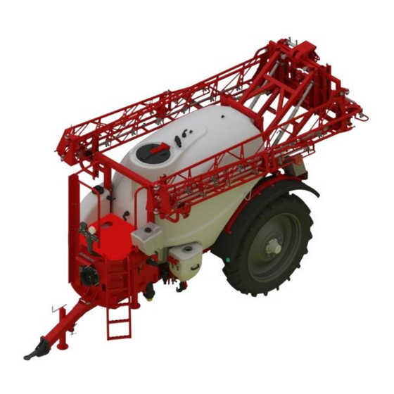
- Page 1 TRAILED TRACTOR SPRAYERS AGS 2500/3000 EN-HP AND SPRAYING BOOMS 12m-HP, 15m-HP, 16m-HP, 18m-HP, 21m-HP, 24m-HP INSTRUCTIONS FOR USE rev.2016/12 AGROMEHANIKA reserves the right to design modifications or product changes, without any liabilities to inform the customer before and after each change.
-
Page 3: Table Of Contents
INDEX GENERAL ......................1 HEALTH-SAFETY WARNINGS AND MEASURES ..........2 Safety signs ..............................2 Maintenance of safety signs ......................... 2 Readiness for danger ........................... 2 Removing unauthorized persons ........................ 2 Safety in handling with chemical products ....................3 Labels for danger, according to danger level .................... 4 Danger of mechanical injuries ........................ - Page 4 Nozzles for cleaning main tank interior ....................24 Suction filter ............................... 24 7.9.1 Cleaning of filter insert ........................24 7.10 Filling container with lifting parallelogram ..................25 7.10.1 Filling container functioning ......................26 7.10.2 Nozzle for rinsing packaging ......................26 7.11 Description of valve settings for spraying or cleaning ................
- Page 5 10.7.7 Swing frame and boom hinges ...................... 49 10.7.8 Boom opening mechanism ......................49 10.7.9 Setting position of booms and opening bar ................... 50 10.7.10 Safety boom and spring slider ....................... 53 10.8 Operation description ........................... 54 10.8.1 Opening spraying equipment ......................54 10.8.2 Closing spraying equipment ......................
- Page 6 Nozzle selection ........................... 116 15.5.2 Selecting appropriate speed and working pressure ..............116 15.6 Different calculations .......................... 116 COMBINATION MATRIX ................117 16.1 Combination matrix AGS 2500 EN-HP ..................... 117 16.2 Combination matrix AGS 3000 EN-HP ..................... 118 NOTES ......................119...
- Page 7 EC DECLARATION OF CONFORMITY Manufacturer: AGROMEHANIKA, proizvodnja in trgovina Kranj d.d. Hrastje 52 a, KRANJ, SLOVENIJA declares that the products: SPRAYER AGS 2500 EN/HP SPRAYER AGS 3000 EN/HP have been manufactured in accordance with: 1. Machine directive 2006/42/EC and; 2. Directive 2009/127/EC amending Directive 2006/42/EC as regards the machinery for pesticide application;...
- Page 9 We would like to thank you for your trust, which you have shown by buying the sprayer appliance for chemical plant protection of the company AGROMEHANIKA. The reliability and efficiency of the appliance depends on how you will take care of the appliance. We advise you to read and consider this instruction manual carefully before connecting the appliance to the tractor.
- Page 10 VIII...
-
Page 11: General
AGS 2500/3000 EN-HP USER MANUAL – rev.2016/12 GENERAL Sprayer device is designed and constructed for applying chemical products in water-based solution, which are normally used for chemical protection of crops, on field crops. Construction design enables access to all vital elements of the sprayer and easy handling. Robust construction, quality component parts and a great deal of additional equipment enable the user to work reliably and use spraying agents and energy optimally. -
Page 12: Health-Safety Warnings And Measures
USER MANUAL – rev.2016/12 AGS 2500/3000 EN-HP HEALTH-SAFETY WARNINGS AND MEASURES 2.1 Safety signs Sign on the left is a warning safety sign and is normally located on the machine with other signs. Respect instructions for safe work and act accordingly in extreme situations. -
Page 13: Safety In Handling With Chemical Products
AGS 2500/3000 EN-HP USER MANUAL – rev.2016/12 2.5 Safety in handling with chemical products Handle chemical products extremely carefully, to avoid potential injuries and dangers to health, as well as to the environment: Be very careful, when handling chemical products. Ensure that you do not have direct contact with chemical products. -
Page 14: Labels For Danger, According To Danger Level
USER MANUAL – rev.2016/12 AGS 2500/3000 EN-HP If you have had an accident with a chemical product, we propose the following safety measures: eyes and skin: rinse with plenty of clean water, throat and oesophagus: drink water (not milk!!!), ... -
Page 15: Dangers, Caused By Liquids Under High Pressure
AGS 2500/3000 EN-HP USER MANUAL – rev.2016/12 2.8 Dangers, caused by liquids under high pressure Liquids, leaking from the pipes, can be under high pressure and can cause injuries to your skin, and cause dangerous injuries, if they spread under your skin. Never try to dismount a hydraulic pipe or any other of the hydraulic installation as long as this one is under high pressure. -
Page 16: Personal Protection
USER MANUAL – rev.2016/12 AGS 2500/3000 EN-HP 2.10 Personal protection Machine operator must use well closed clothing and effective protection equipment during work. The operator can come in contact with chemicals through his or her skin, mouth or nose. If you do not work safely even the best protection equipment cannot be of any use to you. -
Page 17: Skin Protection
AGS 2500/3000 EN-HP USER MANUAL – rev.2016/12 Never check the efficiency of the filter by smelling: certain poisonous elements are odourless, the concentration of the poison cannot always be noticed by human nose, smelling of certain elements can damage the nasal mucous membrane. ... -
Page 18: Safe Maintenance
USER MANUAL – rev.2016/12 AGS 2500/3000 EN-HP The sprayer pump receives the power from the connecting shaft of the tractor by means of the cardan shaft. Drive parts can cause serious injuries so, in order to avoid that , follow the instructions below: ... -
Page 19: Procedures In Accidents With Chemicals
AGS 2500/3000 EN-HP USER MANUAL – rev.2016/12 Sprayer, connected to the tractor, can only be transported on the road, when the reservoir contains no chemical products. Connect the sprayer to the tractor only if the load on the wheels does not exceed the set maximum weight. - Page 20 USER MANUAL – rev.2016/12 AGS 2500/3000 EN-HP SAFETY SIGNS ON MACHINE AND INSTRUCTIONS FOR USE Machine and instructions for use contain safety and warning signs. Take a closer look to ensure your safety. Follow instructions and guidelines, referring to safety measures, given in the previous chapter.
- Page 21 AGS 2500/3000 EN-HP USER MANUAL – rev.2016/12 Learn how to operate the machine well and never allow people to operate the machine who are not familiar with the instructions manual! The table below contains descriptions of different safety signs. Warning: CE declaration of conformity Presence of poisonous chemical products!
-
Page 22: Machine Description
USER MANUAL – rev.2016/12 AGS 2500/3000 EN-HP MACHINE DESCRIPTION Sprayers type AGS 2500 EN-H and AGS 3000 EN-H have a modern design with a chemically resistant polyethylene tank, with rounded edges, smooth interior walls and a sloping bottom. The construction ensures great centre of gravity, good crop protection mixing, complete emptying of the tank and easy cleaning. -
Page 23: Machine Identification
AGS 2500/3000 EN-HP USER MANUAL – rev.2016/12 4.2 Machine identification 4.2.1 Machine identification plate Attached to sprayer chassis and provides following important information: manufacturer's address and country of origin, product type, model, rated tank volume, empty machine weight, allowed total weight, maximum allowed work pressure, production year, serial number,... -
Page 24: Sprayer Component Parts
USER MANUAL – rev.2016/12 AGS 2500/3000 EN-HP 4.3 Sprayer component parts Figure 2 SPRAYER COMPONENT PARTS page... - Page 25 AGS 2500/3000 EN-HP USER MANUAL – rev.2016/12 page...
-
Page 26: Additional Equipment
USER MANUAL – rev.2016/12 AGS 2500/3000 EN-HP Basic equipment of the also includes electronic regulation AG-TRONIK. Spraying sprayer equipment is installed on the and fitted with nozzle holders TRI-JET, with nozzles sprayer divided into 5 sections. Control of hydraulic equipment is performed by tractor hydraulics with connection to control panel. -
Page 27: Connecting Sprayer To Tractor
AGS 2500/3000 EN-HP USER MANUAL – rev.2016/12 CONNECTING SPRAYER TO TRACTOR Sprayers AGS 2500EN-HP and AGS 3000EN-HP are constructed for connection to tractor’s lower connection (towing eyes 40mm (6) are replaceable). Fixed drawbar is length and height adjustable, so the can be connected on different tractors. - Page 28 USER MANUAL – rev.2016/12 AGS 2500/3000 EN-HP Lift the support leg of the (figure 4) by rotating the handle (2), unhook the pin (2), sprayer remove the bolt (3), move the support leg (1) on the holder of support leg on the base, insert bolt and pin and use the handle to lift the bottom part of the support leg.
-
Page 29: Drive – Cardan Shaft (Not Included)
AGS 2500/3000 EN-HP USER MANUAL – rev.2016/12 DRIVE – CARDAN SHAFT (NOT INCLUDED) 6.1 Safety of the user WARNING: To avoid accidents and personal injuries, follow these recommendations and safety regulations! Before mounting (connecting of the cardan shaft to the tractor and the ) the sprayer drive shaft –... - Page 30 USER MANUAL – rev.2016/12 AGS 2500/3000 EN-HP 7. Mount the cardan shaft between the tractor and the sprayer. 8. To ensure a long reliability of the cardan shaft, avoid angles greater than 15°. 9. When using safety cardan shafts, fit an “ALLEN” bolt with torque of 40 Nm. Check the torque after two (2) minutes of operation.
-
Page 31: Detailed Description Of Sprayer Components
AGS 2500/3000 EN-HP USER MANUAL – rev.2016/12 DETAILED DESCRIPTION OF SPRAYER COMPONENTS Sprayer chassis is of welded steel construction with a fixed tank and, in the front part, BM pump, centrifugal pump, pressure filter and tank level indicator. On the left part of the sprayer are valves for sprayer control, suction filter, filling container with parallelogram and tank for washing hands. -
Page 32: Rinsing Tank
USER MANUAL – rev.2016/12 AGS 2500/3000 EN-HP WARNING: Use protective equipment when handling crop protection liquids! The cover consists of one part with lever, through which the float valve mechanism for ensuring aeration and prevention of water leaking from the tank on the bottom side. The cover is opened by turning in clockwise direction and closed in reverse order (see marking on the cover). -
Page 33: Mixing Nozzle
AGS 2500/3000 EN-HP USER MANUAL – rev.2016/12 Attach hose 50 mm to fitting (A) and secure with hose clamp. Connect fitting (A) with hose to connection (B) and secure with side levers (see figure 7). Maximum filling capacity is 250 l/min. -
Page 34: Nozzles For Cleaning Main Tank Interior
USER MANUAL – rev.2016/12 AGS 2500/3000 EN-HP 7.8 Nozzles for cleaning main tank interior Nozzles are installed in the main tank and ensure washing the tank interior after completing spraying. They are connected to selection valve on the pressure line, through which, when it is open, they receive required water for cleaning. -
Page 35: Filling Container With Lifting Parallelogram
AGS 2500/3000 EN-HP USER MANUAL – rev.2016/12 7.10 Filling container with lifting parallelogram Filling container is intended for mixing and pumping of crop protection liquid into the main tank. It is mounted on the lifting parallelogram on the side of the main tank, so that mixing-related work is easier. -
Page 36: Filling Container Functioning
USER MANUAL – rev.2016/12 AGS 2500/3000 EN-HP 7.10.1 Filling container functioning Fill the sprayer’s main tank to approximately 1/3 with water, engage pump drive and turn the selection valve on the pressure line as displayed in figure 13, and fill approximately 1/10 of filling container with water, by opening the control valve (7), which supplies the mixing nozzle (3). -
Page 37: Description Of Valve Settings For Spraying Or Cleaning
AGS 2500/3000 EN-HP USER MANUAL – rev.2016/12 7.11 Description of valve settings for spraying or cleaning 7.11.1 Spraying Use valve for discharge from main tank (pos. 17 – figure 18) to direct crop protection liquid towards suction valves (pos. 7 – figure 18). The valve must be opened so that the suction if from the main tank. -
Page 38: Complete Cleaning Of Sprayer
USER MANUAL – rev.2016/12 AGS 2500/3000 EN-HP 7.11.2 Complete cleaning of sprayer Complete cleaning of sprayer includes cleaning of all internal parts of the sprayer: tank, filter, pump, regulator and nozzles. Direct clean water through valve for discharge from the tank (pos. -
Page 39: Partial Cleaning Of Sprayer
AGS 2500/3000 EN-HP USER MANUAL – rev.2016/12 7.11.3 Partial cleaning of sprayer Partial cleaning of sprayer includes cleaning of filter, pump, pressure regulator and nozzles, without changing crop protection liquid concentration in main tank. Switch valve for discharge from additional tank (pos. 16 – figure 18) in direction towards suction valve (pos. 7 –... -
Page 40: Functional Scheme Of Sprayer
USER MANUAL – rev.2016/12 AGS 2500/3000 EN-HP 7.12 Functional scheme of sprayer Figure 18: FUNCTIONAL SCHEME page... - Page 41 AGS 2500/3000 EN-HP USER MANUAL – rev.2016/12 page...
-
Page 42: Additional Equipment
USER MANUAL – rev.2016/12 AGS 2500/3000 EN-HP ADDITIONAL EQUIPMENT 8.1 Hydraulic drawbar As additional equipment, hydraulic drawbar can be installed. Installation is described in the chapter “CONNECTION OF SPRAYER TO TRACTOR”. Hydraulic drawbar is constructed for wheels to follow tractor wheels, which enables easy turning and small turning circle. Complete system enables better control of sprayer and helps when driving on uneven terrain (transverse inclination of field). -
Page 43: Set For External Washing Of Spraying Device
AGS 2500/3000 EN-HP USER MANUAL – rev.2016/12 Figure 20: LIGHT SIGNALLING Figure 21: WARNING SIGN FOR SLOW VEHICLES As required by law, the sprayer is also fitted with a sign for slow vehicles on the rear of the sprayer. 8.3 Set for external washing of spraying device After completing spraying, the spraying device must be cleaned. -
Page 44: Suction Basket With Suction Hose
USER MANUAL – rev.2016/12 AGS 2500/3000 EN-HP Suction basket with suction hose WARNING: When sucking water from a pond, be extremely careful, as you can easily contaminate the water in the pond! The suction basket is intended for sucking water out of ponds, creeks, wells, etc. -
Page 45: Control Before Use
AGS 2500/3000 EN-HP USER MANUAL – rev.2016/12 9.1 Control before use When the pump is not operating, check the oil quantity in the housing of the pump. Also check the oil level every single time before filling the tank. The level must be within the limits which are marked on the oil lid or in the oil pot (depends on the version of the pump). -
Page 46: Piston-Diaphragm Pump Bm 150/20 And Bp 171 K
USER MANUAL – rev.2016/12 AGS 2500/3000 EN-HP 9.4 Piston-diaphragm pump BM 150/20 and BP 171 K Pumps type BM 150/20 (BP 171 K) are low-pressure piston-diaphragm pumps, made of materials that have been tested by the factory. The pumps are suitable for pumping of insecticides or liquid fertilizers which are used in farming. -
Page 47: Instructions In Case Of Damaged Diaphragm
(see chapter “MAINTENANCE AND STORAGE AFTER SEASON – PUMP”). 9.5 Mixing pump C200 Sprayer AGS 2500 EN-HP or AGS 3000 EN-HP is equipped as standard with centrifugal pump, which ensure quality and constant mixing of crop protection liquid in the tank. Mixing pump is connected to the main pump with a V-belt. -
Page 48: Spraying Equipment
USER MANUAL – rev.2016/12 AGS 2500/3000 EN-HP 10 SPRAYING EQUIPMENT Spraying equipment 12-24m-HP (figure 30), is hydraulically side foldable spraying equipment for trailed sprayer type 2500 EN-HP and 3000 EN-HP. Opening and closing from the transportation position into working position and vice-versa is performed with the help of hydraulic cylinders, which enable individual opening or closing of spraying booms. -
Page 49: Sprayer And Spraying Equipment Dimensions
AGS 2500/3000 EN-HP USER MANUAL – rev.2016/12 10.2 Sprayer and spraying equipment dimensions Sprayer and spraying equipment dimensions and other characteristics are provided in the technical sheet (see Technical sheet). Figure 28: SPRAYER AND SPRAYING EQUIPMENT DIMENSIONS Legend: A – length B –... -
Page 50: Components For Controlling Spraying Equipment
USER MANUAL – rev.2016/12 AGS 2500/3000 EN-HP 10.3 Components for controlling spraying equipment 10.3.1 Connection scheme with three quick couplings Figure 29: CONNECTION SCHEME Legend: A. Supply cable + supply plug B. AG-TRONIK C. Electrical connection cabinet D. Control panel E. -
Page 51: Control Panel
AGS 2500/3000 EN-HP USER MANUAL – rev.2016/12 10.3.3 Control panel Control panel is a component part of controlling hydraulics of spraying equipment 12-24 m- HP, and must be installed in an appropriate place in the tractor cabin. It contains graphic display of all working functions, which can be performed with hydraulics. -
Page 52: Connection Hydraulic Hoses With Connection Clamps
USER MANUAL – rev.2016/12 AGS 2500/3000 EN-HP WARNING: Agromehanika is not liable for damage to the tractor, which are caused by mixing oil. 10.3.6 Connection hydraulic hoses with connection clamps For its operation, sprayer AGS 2500/3000 EN-HP requires three standard hydraulic connections. -
Page 53: Connecting The Sprayer To Tractor
AGS 2500/3000 EN-HP USER MANUAL – rev.2016/12 10.4 Connecting the sprayer to tractor Spraying equipment is, upon delivery, installed on the sprayer and factory tested. Installation of sprayer is described in chapter 5. 10.5 Connections to tractor Tractor cabin must be, at a fixed place, fitted with AG-TRONIK (pos. B – figure 28) for control of spraying and control panel (pos. -
Page 54: Properties Of Spraying Equipment 12-24 M-Hp
USER MANUAL – rev.2016/12 AGS 2500/3000 EN-HP spraying equipment and function only when it is folded, when closing the equipment, it must be raised to end position, folded with the help of electrohydraulic control and then lowered onto mechanical safeties, so they become functioning. Pay attention to spraying equipment lie down on the front safeties only, the last need to be raised from 5 to 10 cm! WARNING: Incorrectly folded spraying equipment in transport position does not ensure safety from uncontrolled opening of booms during transport! -
Page 55: Hydraulic Lifting Parallelogram And Vertical Suspension
AGS 2500/3000 EN-HP USER MANUAL – rev.2016/12 10.7.1 Hydraulic lifting parallelogram and vertical suspension Hydraulic lifting parallelogram is the same for all spraying equipment. Hydraulic cylinders operate in one way. Choke valve on distribution cube, which is attached to sprayer’s chassis, ensures lifting speed. -
Page 56: Side Damping
USER MANUAL – rev.2016/12 AGS 2500/3000 EN-HP 10.7.2 Side damping Side forces, which occur during driving on the spraying equipment, are controlled by polyurethane springs, installed between boom holder and fastening holder of the boom. It is important that the springs are equally pre-tensioned, to ensure setting of spraying equipment, in case of side tilting, in original position . -
Page 57: Hydraulic Levelling
AGS 2500/3000 EN-HP USER MANUAL – rev.2016/12 10.7.4 Hydraulic levelling Levelling cylinder is fastened between the swing frame holder and parallelogram fastening. Response of levelling cylinder is set with choke. Hydraulic levelling can set balance position of spraying equipment (horizontal position), as well as parallelism of equipment to the ground in case of sloping terrain. -
Page 58: Side Foldable Boom
USER MANUAL – rev.2016/12 AGS 2500/3000 EN-HP 10.7.6 Side foldable boom Spraying equipment construction enables horizontal folding of booms against the side of the sprayer. Advantages of side folding are smaller transport width and height (see technical sheet). Figure 38: SIDE FOLDABLE BOOMS page... -
Page 59: Swing Frame And Boom Hinges
AGS 2500/3000 EN-HP USER MANUAL – rev.2016/12 10.7.7 Swing frame and boom hinges Fastening of first boom on the swing frame and fastening between booms is two-point. Lower and top hinges have eye bearings and enable boom setting in any position. All bearings are provided with greasing points for greasing eye bearings. -
Page 60: Setting Position Of Booms And Opening Bar
USER MANUAL – rev.2016/12 AGS 2500/3000 EN-HP For final setting of both hydraulic cylinders with booms of spraying equipment, both cylinder have, on the fastening part, a limiting nut (pos. 1 – figure 42) with transverse safety bolts. Limiting nut enables the cylinder to limit the position of boom closing, which is secured after setting with counter-nut. - Page 61 AGS 2500/3000 EN-HP USER MANUAL – rev.2016/12 Boom 2: Verticality of the second boom is set on eye bearings, the same as the first. Top bearing (pos. 1 – figure 44) for open position, bottom eye bearing (pos. 2 – figure 44) for closed position. Parallelism is ensured by bolt connection (pos.
- Page 62 USER MANUAL – rev.2016/12 AGS 2500/3000 EN-HP Opening bar: For correct closing and opening of spraying equipment, good setting of opening bar is important. Otherwise, the spraying equipment may not close or open to end position. Position in open spraying equipment is ensured by bolt connection (pos. 1 – figure 46) on the outer side of equipment –...
-
Page 63: Safety Boom And Spring Slider
AGS 2500/3000 EN-HP USER MANUAL – rev.2016/12 10.7.10 Safety boom and spring slider Rear boom (final) is protected with safety joint and, in case of impact with an obstacle, moves away from the obstacle and returns to original position. Spring slider prevents impact of equipment with the ground in case of sudden tilting of the sprayer! It can be adjusted step-free on the boom according to desire. -
Page 64: Operation Description
USER MANUAL – rev.2016/12 AGS 2500/3000 EN-HP 10.8 Operation description Equipment can be used, when the sprayer and the spraying equipment are correctly connected to the tractor (see chapter “CONNECTING SPRAYER TO TRACTOR”). Connect hydraulic hoses of sprayer to hydraulic connections of tractor and connect AG-TRONIK and control panel for control of hydraulic equipment. -
Page 65: Spraying Sections And Nozzles
AGS 2500/3000 EN-HP USER MANUAL – rev.2016/12 10.8.3 Spraying sections and nozzles All types of equipment are equipped with five sections. Spraying sections are arranged across the equipment so that they enable minimum pressure fall in hoses and best distribution of spraying product to individual nozzle. -
Page 66: Spraying Hoses
USER MANUAL – rev.2016/12 AGS 2500/3000 EN-HP 10.8.6 Spraying hoses Shapes of spraying hoses (PE), used on spraying equipment, type H, are displayed in figure below. They are marked with a number marking. Example: spraying hose 2/2, option of hose connection on the sides. -
Page 67: Ag-Tronik
AGS 2500/3000 EN-HP USER MANUAL – rev.2016/12 11 AG-TRONIK 11.1 AG-TRONIK description AG-TRONIK is processor controlled device for monitoring and automatic balancing of spray on machines for chemical protection of plants. It is used on combination with pressure regulator. Take a few moments to familiarize yourself with buttons, displays and some component parts of AG-TRONIK. - Page 68 USER MANUAL – rev.2016/12 AGS 2500/3000 EN-HP Figure 53: AG-TRONIK COMPONENTS Legend: 1. DISPLAY 2. Key ON/OFF 3. Key AUTOMATIC 4. Key PRESSURE INCREASE (manual control) 5. Key PRESSURE DECREASE (manual control) 6. Key PROGRAM 7. Key FUNCTION 8. Key BYPASS VALVE ON/OFF 9.
-
Page 69: Function Diagram Of The System
AGS 2500/3000 EN-HP USER MANUAL – rev.2016/12 11.2 Function diagram of the system Figure 54: FUNCTIONAL DIAGRAM SYSTEM AG-TRONIK receives information, required for calculation of actual liter per hectare from: Flow sensor, which is built in section side of regulator; ... -
Page 70: Description Of The Display
USER MANUAL – rev.2016/12 AGS 2500/3000 EN-HP 11.3 Description of the display When you press »ON/OFF« the display turns on. First, the welcome screen is displayed for a few seconds, and then the basic display is displayed. The basic display contains the following information: Legend: 1. -
Page 71: Ag-Tronik Keys Description
AGS 2500/3000 EN-HP USER MANUAL – rev.2016/12 11.4 AG-TRONIK keys description Keys for turning on, AUTO, MAIN and sections have a LED diode next to the key, which lights up or blinks, when the key is on. LEDs for AUTO and MAIN are red, key for turning on, has a green LED diode, keys for sections have two-colour LED diodes (green and red). -
Page 72: Operation Description – Manual Control
USER MANUAL – rev.2016/12 AGS 2500/3000 EN-HP 11.5 Operation description – manual control In the manual control spraying is provide manually. Between work we can increase and decrease the pressure and, in this context change hectare consumption, in short, the spraying takes place without the operation of the computer or. -
Page 73: Preparation For Spraying
AGS 2500/3000 EN-HP USER MANUAL – rev.2016/12 Appropriateness of spraying according to weather conditions, If the conditions above are met, then spraying with AG-TRONIK is very simple. The operator must only keep driving in a steady manner, the speed being in accordance with nozzle functioning capability (ST and LU from 1.5 bar- 5 bar;... -
Page 74: Programming
USER MANUAL – rev.2016/12 AGS 2500/3000 EN-HP 11.7 Programming To enter program "PROGRAMMING", use quick menus. Menus are located in top right part of display. Red frame marks icon of individual chapter. QUICK MENUS "PROGRAMMING" Use button to select between menus PROGRAMMING or ANALYSES: Figure 56: ANALYSYS Figure 55: PROGRAMMING Icons have the following meaning or mark chapters:... -
Page 75: Hectare Consumption
AGS 2500/3000 EN-HP USER MANUAL – rev.2016/12 Access required icon by moving left and up with button , right and down with button . use confirmation button to select correct chapter. 11.7.1 Hectare consumption Select icon and use confirmation button to confirm it. -
Page 76: Filling Of Tank
USER MANUAL – rev.2016/12 AGS 2500/3000 EN-HP 11.7.2 Filling of tank With the window “FILLING OF TANK” you basically set the content of chemical, which you have prepared in the tank. By setting the value you are basically setting the quantity of chemical on the liter scale of AG-TRONIK. -
Page 77: Erasing Daily Counters Of Spray Consumption [L], Surface Area [Ha] And Path [Km]
AGS 2500/3000 EN-HP USER MANUAL – rev.2016/12 11.7.3 Erasing daily counters of spray consumption [l], surface area [ha] and path [km] To erase daily counters, select icon and confirm it with confirmation button The display shows: If you want to erase an individual counter, use button to move selection window to value, which you want to erase. -
Page 78: Flow Constant
USER MANUAL – rev.2016/12 AGS 2500/3000 EN-HP no suitable cable connection between AG-TRONIK and GPS device or the GPS device is not functioning properly or there are not enough satellite signals for operation. If the symbol is not flashing, connection between AG-TRONIK and GPS device functions perfectly and devices communicate with each other. - Page 79 AGS 2500/3000 EN-HP USER MANUAL – rev.2016/12 New constant: If you know the flow constant or it is shown on the flow sensor, then choose the new constant menu. Choose the line NEW CONSTANT and press key to open the following window: If you wish to enter a change of value, press key .
- Page 80 USER MANUAL – rev.2016/12 AGS 2500/3000 EN-HP Option of entering following parameters is available: Number of operating nozzles [no.nozzles] Flow/nozzle [flow/n] Common flow through nozzles [flow] When you open the window KNOWN FLOW, the value in number of nozzles is framed. If you wish to change the number of nozzles, press key to choose the line (frame starts to blink).
- Page 81 AGS 2500/3000 EN-HP USER MANUAL – rev.2016/12 Correction: Constant correction of flow sensor is the most accurate measurement. It is done, when the first tank has been sprayed. The positive side of correction is that a measurement with chemical is performed, therefore correct density of chemical is regarded, and the down side is that it can only be executed, when the first tank is emptied.
-
Page 82: Speed Constant
USER MANUAL – rev.2016/12 AGS 2500/3000 EN-HP 11.7.6 Speed constant Speed constant is the number of impulses (imp/km), which the speed sensor forwards to AG- TRONIK at a distance of 1 km. It depends on the circumference or diameter of wheel and number of marks on the wheels. - Page 83 AGS 2500/3000 EN-HP USER MANUAL – rev.2016/12 Speed constant was calculated with the equation above. This is input in AG-TRONIK. In speed constant menu choose line NEW CONSTANT and press key to open the following window: If you wish to input value change, press key .
- Page 84 USER MANUAL – rev.2016/12 AGS 2500/3000 EN-HP Distance: Distance can also be input by measuring the distance beforehand. Drive the distance with tractor and input it in AG-TRONIK. To do this, follow this procedure: Move the tractor to the start of the measured distance. Stop the tractor and choose line DISTANCE in menu SPEED CONSTANT.
-
Page 85: Working Width
AGS 2500/3000 EN-HP USER MANUAL – rev.2016/12 11.7.7 Working width To enter window "WORKING WIDTH", select icon and confirm it with confirmation button . Display shows: Description: d1-d7 – width of individual sections D – total length of spraying equipment One nozzle represents 0.5 m of working width, if the nozzles are 0.5 m apart. - Page 86 USER MANUAL – rev.2016/12 AGS 2500/3000 EN-HP Window includes signs for: year month hour minute language minimum speed simulation flow measuring protocol Use buttons to select/move selection frame on the list. When desired line is selected, press button and frame starts flashing.
- Page 87 AGS 2500/3000 EN-HP USER MANUAL – rev.2016/12 Simulation: Simulation is primarily intended for presentation and training or explaining functioning of AG-TRONIK. Simulation is activated by changing value to ON, and deactivated by changing value to OFF or turning off AG-TRONIK. When simulation is activated, letter S flashes in the basic menu.
-
Page 88: Analyses
USER MANUAL – rev.2016/12 AGS 2500/3000 EN-HP pressure sensor is installed, pressure is displayed on basic image. Pressure is displayed independent of selected flow measuring protocol. Enter pressure protocol in subprogram general settings, where you position selection frame in line REG MODEL. As default, FLOW is selected (measuring with flow sensor). Press button and selection frame starts flashing. -
Page 89: Tank
AGS 2500/3000 EN-HP USER MANUAL – rev.2016/12 Icons carry following meaning or mark chapters: 1. TANK (overview of spray status in tank and remaining surface [ha] according to path [km], current capacity of spraying chemicals is sufficient) 2. FLOW ANALYSIS (current analysis of nozzle flow on spray) 3. -
Page 90: Flow Analysis
USER MANUAL – rev.2016/12 AGS 2500/3000 EN-HP Currently: shows current state of chemicals in the tank. The value is correct, if you have set the value correctly before the start of spraying and if the flow sensor is correctly calibrated. Soffices: show treated area, which can be sprayed with current state of chemical in the tank, by assuming that spraying parameters will not be modified during work. - Page 91 AGS 2500/3000 EN-HP USER MANUAL – rev.2016/12 In menu “WORK”, start and end of analyses are defined, but also the following can be entered: Lot name Nozzle size Nozzle type Culture Chemical 1 Chemical 2 ...
- Page 92 USER MANUAL – rev.2016/12 AGS 2500/3000 EN-HP Speed constant (imp/km): 4320 Speed constant Enter window "WORK" by selecting icon and confirming it with confirmation button . The display shows: Press button to confirm window START/CONTINUE. New window opens: If you decide not to monitor spraying with analysis, select and confirm "X". Window returns to previous window.
- Page 93 AGS 2500/3000 EN-HP USER MANUAL – rev.2016/12 Nozzle type Culture Chemical 1 Chemical 2 Chemical 3 Chemical 4 AG-TRONIK leads us through the menus to enter data step by step. When you select “NEW” and confirm it with key , new window for input of lot name opens.
- Page 94 USER MANUAL – rev.2016/12 AGS 2500/3000 EN-HP Similar as with window for selection of nozzle, select an appropriate nozzle type from the drop-down list by pressing key or key . Confirm with key . By confirming nozzle type, new window culture opens, where you input culture: Culture name input is done like lot name input.
- Page 95 AGS 2500/3000 EN-HP USER MANUAL – rev.2016/12 Press confirmation button to activate analysis. Briefly, ANALYSIS IN PROGRESS is displayed under the bottom line. Continue work: If you have changed nozzle and/or type of chemical and/or chosen another nozzle type or just continued work on the same lot after a few days, without conducting analysis on other lots, all data does not need to be input in AG-TRONIK;...
- Page 96 USER MANUAL – rev.2016/12 AGS 2500/3000 EN-HP If you have chosen not to cancel the analysis, simply choose NO and return to the previous window. If you select " " and confirm with confirmation button , new window is displayed: In window, AG-TRONIK asks if you wish to write analysis to SD memory card.
-
Page 97: Analysis
AGS 2500/3000 EN-HP USER MANUAL – rev.2016/12 Move selection frame to name, which you want to rename, and press confirmation button to open window: Renaming is the same as name input in chapter "new work". Select individual letters from the list of letters below. - Page 98 USER MANUAL – rev.2016/12 AGS 2500/3000 EN-HP Use button to move around analysis list. The display shows data in two lines. page...
- Page 99 AGS 2500/3000 EN-HP USER MANUAL – rev.2016/12 Data, written in analysis, are the following: ANALYSIS: Lot name: NOZZLE: NOZZLE TYPE: CULTURE: CHEMICAL 1: CHEMICAL 2: CHEMICAL 3: CHEMICAL 4: START: STOP: XXXXXXXX: AUTOMATIC: Time of work: Travelled distance (km): Spraying time : Set consumption (l/ha): Average consumption (l/ha): Chemical consumption (l):...
-
Page 100: General
USER MANUAL – rev.2016/12 AGS 2500/3000 EN-HP 11.8.5 General Windows shows information about data transfer, settings... and is intended for servicing. They are important for the user, if he wishes to reset AG-TRONIK to factory settings. Enter window "GENERAL" by selecting icon and confirming it with confirmation button . -
Page 101: Data Transfer To Computer
AGS 2500/3000 EN-HP USER MANUAL – rev.2016/12 11.9.2 Data transfer to computer When analyses are written on the card, they can be viewed on a personal computer. You need a SD card reader, if you do not have an appropriate SD card slot on your computer. Content on SD card is read by the computer automatically. - Page 102 USER MANUAL – rev.2016/12 AGS 2500/3000 EN-HP Excel printout: Excel printout is a better option. Here you can add up specific fields or edit them in another manner. When transferring, be careful to transfer data to Excel correctly. First, open program Excel and find the file, where analyses are written and confirm it.
-
Page 103: Gps Output
Bottom (8-pole) connector is intended for connection of GPS device, with which you can control the sprayer precisely to section. Before purchasing GPS device, consult with authorized dealer for Agromehanika, if the GPS device is compatible with AG-TRONIK. -
Page 104: Gps Serial Communication
USER MANUAL – rev.2016/12 AGS 2500/3000 EN-HP GPS OUTPUT 12V GPS SERIAL COMMUNICATION 11.10.2 GPS serial communication GPS device, which can control individual sections of spraying equipment, is connected to bottom connector. When connecting, be careful to correctly plug in male connector of GPS device in AG-TRONIK. - Page 105 AGS 2500/3000 EN-HP USER MANUAL – rev.2016/12 If the green diode is on, this means that GPS device allows spraying and the operator of spraying device has manually turned off an individual section. Operation of spraying device is, in addition to LED diodes, also shown graphically on display. If LED diode is on, it means that the section is closed and that it is on a part of already sprayed surface.
-
Page 106: Pressure Regulator
USER MANUAL – rev.2016/12 AGS 2500/3000 EN-HP 12 PRESSURE REGULATOR Pressure regulator with bypass regulation is by far the most suitable for trailed sprayers, because of better response time of distribution valves when spraying. Bypass regulation has its regulation part separated from distribution valves. Regulation part is located closer to the pump, suction and pressure collector, while the distribution valve is located closer to the nozzle, so the response time of the distribution valve can be better/ is as big as it can be. -
Page 107: Designation Of The Regulator
AGS 2500/3000 EN-HP USER MANUAL – rev.2016/12 LEGEND: 1. Regulation valve 2. Pressure gauge 3. Self-cleaning pressure filter 4. Section valve 5. Flow meter 6. Bypass valve Regulation valve with filter is normally installed in the front part of spraying device, close to pump and optional 5-way pressure valve. -
Page 108: Section (Distribution) Valves Ec-06
USER MANUAL – rev.2016/12 AGS 2500/3000 EN-HP tank through valve on the bottom of the filter (red wheel). By turning the wheel in counter- clockwise direction, you open the flow through filter valve. Valve is closed during spraying. If you want to clean the filter, open the valve and create flow through pressure filter in the tank. -
Page 109: Flow Meter
Such accessories require calibration of flow gauge. Connection of electromagnetic gauge to electrical cabinet is different than standard connection. Before installing such gauge in pressure regulator, consult technical staff of Agromehanika. page... -
Page 110: Pressure Sensor - Option
USER MANUAL – rev.2016/12 AGS 2500/3000 EN-HP 12.3.4 Pressure sensor - option Instead of measuring flow with flow gauge, flow can be indirectly measured with pressure sensor. Pressure sensor is installed in pressure gauge position. Measuring and readout of pressure are shown on basic image of display of AG-TRONIK. -
Page 111: Electrical Connection Cabinet
In case of short-term overload, fuse disengages and reengages in the next moment. If there is a serious motor fault and the fuse does not engage, fault must be remedied by authorized service of Agromehanika. Speed sensor is connected to bottom part of connection cabinet (4-pole connector). Flow sensor is connected to connection cabinet through connection clamps. -
Page 112: Regulator Maintenance
4. It is obligatory to unscrew the pressure gauge and keep it in a warm place. 12.5 Parameters setting in AG-TRONIK program Technicians of Agromehanika input parameters, required for spraying in AG-TRONIK and save these parameters in factory setting. AG-TRONIK is accompanied with a sheet of parameters –... - Page 113 AGS 2500/3000 EN-HP USER MANUAL – rev.2016/12 PARAMETER VALUE NOTE imp/l Imp/km l/ha page...
-
Page 114: Maintenance
USER MANUAL – rev.2016/12 AGS 2500/3000 EN-HP 13 MAINTENANCE 13.1 Sprayer cleaning After each use, the sprayer must be thoroughly cleaned. The best way to use any excess insecticide is to dilute it with water and spray it on the same surface again. The concentration should be at least 10% (10 units of water per one unit of insecticide), the spraying speed slightly faster and the spraying pressure slightly lower (1.5 bar, depending on the nozzle). -
Page 115: Maintenance And Storage After Season
AGS 2500/3000 EN-HP USER MANUAL – rev.2016/12 After cleaning the sprayer with a detergent, fill at least 1/5 of the tank with clean water and repeat the cleaning process. Make sure that you have cleaned all elements that have come in contact with the insecticide or the detergent. -
Page 116: Drive Shaft – Cardan
USER MANUAL – rev.2016/12 AGS 2500/3000 EN-HP Therefore, in case of poor sealing or leaking: DO NOT TIGHTEN the joint too hard, since you can easily damage it. Take the joint apart and check the condition and position of the sealing or the O-ring, clean and grease it and reassemble the joint. -
Page 117: Procedure Of Protecting The Sprayer With Anti-Freezing Agent
AGS 2500/3000 EN-HP USER MANUAL – rev.2016/12 This requires: either removing water from the pump, the regulator, the hoses, the filters and other elements…; either storing the device in a warm space; or using an agent against freezing (antifreeze). 13.2.10 Procedure of protecting the sprayer with anti-freezing agent After you have finished cleaning the spraying device, completely empty the tank and pour at least 10 litres of antifreeze agent (a mixture of water and antifreeze) and turn on the pump. -
Page 118: Bolt Tightening Torque
USER MANUAL – rev.2016/12 AGS 2500/3000 EN-HP 13.3 Bolt tightening torque Wrench Bolt quality Thread size 10.9 12.9 1.4 Nm 2.3 Nm 2.9 Nm 4.1 Nm 4.9 Nm 2.8 Nm 4.5 Nm 6.0 Nm 8.5 Nm 10 Nm 4.8 Nm 7.7 Nm 10 Nm 14 Nm... -
Page 119: Technical Data
AGS 2500/3000 EN-HP USER MANUAL – rev.2016/12 14 TECHNICAL DATA 14.1 Designation Spraying devices are designated as follows: Example: AGS 3000 EN-HP; BM 150; PR-3ECFM/7EC+2; 18m-HP; AGS..Abbreviation for sprayer 3000..Rated tank volume EN-HP..Version (sprayer with additional tanks for cleaning and washing hands) BM 150... -
Page 120: Dimensions And Weight
USER MANUAL – rev.2016/12 AGS 2500/3000 EN-HP 14.3 Dimensions and weight page... -
Page 121: Removing The Sprayer
AGS 2500/3000 EN-HP USER MANUAL – rev.2016/12 14.4 Removing the sprayer Once the spraying device cannot be used anymore, you will have to clean it completely, take it apart and sort the individual components of the sprayer by material. The components must be handed over to an organisation which deals with waste materials. -
Page 122: General Instructions For Spraying
USER MANUAL – rev.2016/12 AGS 2500/3000 EN-HP 15 GENERAL INSTRUCTIONS FOR SPRAYING WARNING: Sprayer is NOT SUITABLE FOR USE LIQUID FERTILIZER! In case of emergency use, we recommend consultation with our technical service! For a successful spraying, the appropriate water quantity, right nozzle selection and a precise consumption calculation are of major impotence. -
Page 123: Nozzle Types In Farming
AGS 2500/3000 EN-HP USER MANUAL – rev.2016/12 15.1 Nozzle types in farming 15.1.1 Nozzle types with a flat jet This kind of nozzles is principally used for spraying with herbicides, insecticides and fungicides. The insecticide is precisely distributed along the whole working range of the nozzle. -
Page 124: Wind Influence
USER MANUAL – rev.2016/12 AGS 2500/3000 EN-HP Spraying parameter settings should be such that the overlap of jets between the two nozzles is minimal. A – Distance between the nozzles H – Height of nozzles above the crops Δ – Sprinkling angle 15.2 Wind influence If possible, avoid spraying in windy conditions. -
Page 125: Tables Of Nozzle Flow
AGS 2500/3000 EN-HP USER MANUAL – rev.2016/12 15.4 Tables of nozzle flow TABLE 1: Flow rate of LECHLER spraying nozzles (v l/min): WARNING: The nozzle flow rates are always the same for the same colour markings of different types (ST, LU, AD, ID, TR, etc.) and materials. -
Page 126: Use Of Tables
USER MANUAL – rev.2016/12 AGS 2500/3000 EN-HP 15.5 Use of tables 15.5.1 Nozzle selection Example: You have the following data: desired consumption per hectare of 400 l working speed: 6 km/h ---------------------------------------------------------------------------------------------------------------- 1. In the speed column for 6 km/h of table 2 find the desired consumption per hectare 400 l/ha. 2. -
Page 127: Combination Matrix
AGS 2500/3000 EN-HP USER MANUAL – rev.2016/12 16 COMBINATION MATRIX 16.1 Combination matrix AGS 2500 EN-HP page... -
Page 128: Combination Matrix Ags 3000 En-Hp
USER MANUAL – rev.2016/12 AGS 2500/3000 EN-HP 16.2 Combination matrix AGS 3000 EN-HP page... -
Page 129: Notes
AGS 2500/3000 EN-HP USER MANUAL – rev.2016/12 17 NOTES page... - Page 130 USER MANUAL – rev.2016/12 AGS 2500/3000 EN-HP page...
Need help?
Do you have a question about the AGS 2500 EN-HP and is the answer not in the manual?
Questions and answers