Table of Contents
Advertisement
Quick Links
PRODUCT LITERATURE
Lennox Industries Inc.
Dallas, Texas
Tested For 50 psi.
Working Pressure
ASME
INSTALLATION
INSTRUCTIONS
OWB86-3
OWB86-4
OWB86-5
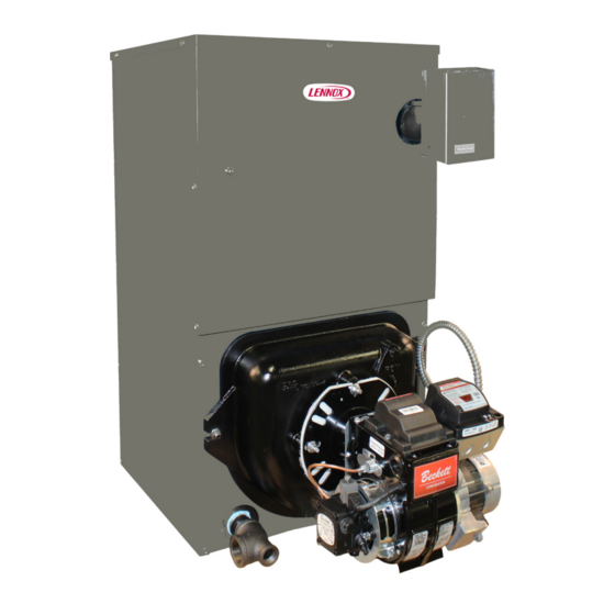
OIL FIRED BOILER
RETAIN THESE INSTRUCTIONS FOR
FUTURE REFERENCE
These instructions must be affixed on or
adjacent to the boiler.
!
WARNING
Improper installation, adjustment, alteration,
service, or maintenance could result in death
or serious injury. Refer to this manual for
assistance. For additional information consult
a qualified installer, service agency, or the oil
supplier.
PN 240013016, Rev. A [07/31/2020]
Advertisement
Table of Contents

Related Manuals for Lennox OWB86-3


Summary of Contents for Lennox OWB86-3
- Page 1 INSTALLATION INSTRUCTIONS PRODUCT LITERATURE Lennox Industries Inc. Dallas, Texas OWB86-3 OWB86-4 OWB86-5 OIL FIRED BOILER RETAIN THESE INSTRUCTIONS FOR FUTURE REFERENCE These instructions must be affixed on or adjacent to the boiler. WARNING Improper installation, adjustment, alteration, service, or maintenance could result in death or serious injury.
-
Page 2: Table Of Contents
TABLE OF CONTENTS Boiler Ratings And Capacities ......3 Introduction OWB boiler is a natural draft oil fired hot water boiler Safety Notices ............. 4 comprised of cast iron sections. Boiler is available with 3, 4, Safe Installation And Operation ......5 or 5 cast iron sections. -
Page 3: Boiler Ratings And Capacities
(inches) BOILER MODEL A.F.U.E. CHIMNEY CAPACITY RATING SEC. SIZE/ *Mbh WATER +gph *Mbh HEIGHT *Mbh OWB86-3 0.80 86.0 8” X 8” X 15” 14½ OWB86-4 1.25 86.0 8” X 8” X 15” 17¾ 9⅝ OWB86-5 1.55 86.0 8” X 8” X 15”... -
Page 4: Safety Notices
SAFETY NOTICES FOR YOUR SAFETY READ BEFORE OPERATING Boiler installation shall be completed by qualified agency. DANGER WARNING Fire, explosion, asphyxiation and electrical shock hazard. Improper installation could result in death or serious injury. Read this manual and understand all requirements before beginning installation. WARNING Do not tamper with or use this boiler for any purpose other than its intended use. -
Page 5: Safe Installation And Operation
SAFE INSTALLATION AND OPERATION Before servicing, allow boiler to cool. Always shut off WARNING any electricity and oil to boiler when working on it. Combustion chamber insulation in this product Inspect oil line and connections for leaks. contains ceramic fiber material. Ceramic fibers can Be certain oil burner nozzle is the size required. -
Page 6: Locating The Boiler
LOCATING THE BOILER Place boiler in location centralized with the piping system Complete Prior To Installing Boiler. and as close to chimney as possible. A. Verify you have selected the right size boiler with Boiler must be level. If necessary use metal shims proper capacity. - Page 7 LOCATING THE BOILER Figure 3 - Boiler With Piping System PN 240013016, Rev. A [07/31/2020]...
-
Page 8: Fresh Air For Combustion
FRESH AIR FOR COMBUSTION EXAMPLE 2: Boiler Located in Confined Space WARNING All Air from Inside the Building: Confined space shall Asphyxiation, fire hazard. Do not obstruct air be provided with two permanent openings communicating openings to combustion area. Follow instructions directly with additional room(s) of sufficient volume so below, to maintain adequate combustion air. - Page 9 FRESH AIR FOR COMBUSTION All Air from Outdoors: Confined space shall be 3. When communicating with outdoors through provided with two permanent openings, one commencing horizontal ducts, each opening shall have minimum within 12 inches of top and commencing within 12 inches of free area of one square inch per 2,000 Btu per bottom of enclosure.
-
Page 10: System Piping
SYSTEM PIPING Installation of boiler for new heating system, Figure 6a - Safety Relief Valve Installation Install all of radiation units (panels, radiators, baseboard, or tubing) and supply and return mains first. After all heating system piping and components have been installed, make final connection of system piping to boiler. - Page 11 SYSTEM PIPING Low Design Water Temperature Systems Figure 7 - Bypass Piping Arrangement (Below 140° F) And Large Water Content Systems Diagram • Significant condensation may form in this boiler and/ > LOW DESIGN WATER TEMPERATURE or venting system if boiler is operated with return SYSTEMS temperatures of less than 120°F.
- Page 12 SYSTEM PIPING Figure 8 - System Piping Arrangement Zoning With Zone Valves > CIRCULATOR ON SUPPLY PIPING PUMPS AWAY FROM EXPANSION TANK NOTE: CIRCULATOR MAY ALSO BE INSTALLED ON RETURN PIPING. > PIPING ARRANGED FOR “POWER PURGING” AIR OUT OF SYSTEM PIPING, REFER TO THIS MANUAL’S SECTION ON “FILLING THE SYSTEM WITH WATER”...
- Page 13 SYSTEM PIPING Figure 9 - System Piping Arrangement Zoning With Circulators > CIRCULATOR ON SUPPLY PIPING PUMPS AWAY FROM EXPANSION TANK > PIPING ARRANGED FOR “POWER PURGING” AIR OUT OF SYSTEM PIPING, REFER TO THIS MANUAL’S SECTION ON “FILLING THE SYSTEM WITH WATER”...
- Page 14 SYSTEM PIPING Figure 10 - System Piping Arrangement Alternate Near Boiler Piping > PER THIS MANUAL, USE OPTION #2 IN > DIAPHRAGM EXPANSION TANK MOUNTED “FILLING THE SYSTEM WITH WATER” OFF THE BOILER > THIS PIPING ARRANGEMENT CAN BE USED >...
- Page 15 Input Rating Model (MBH) DANGER Rate (gph) (gpm)‡ Scald, Burn Hazard! Temperatures exceeding 120°F OWB86-3 0.80 3.05 will cause severe burns or death. Use of water OWB86-4 1.25 3.50 tempering device or mixing valve may be required by the Authority having jurisdiction, follow all codes OWB86-5 1.55...
-
Page 16: Antifreeze In The System
ANTIFREEZE IN THE SYSTEM Antifreeze added to boilers must be nontoxic, and PIPING WATER VOLUMES must be of type specifically intended for use in closed COPPER PIPE STEEL PIPE hydronic heating systems. Under no circumstances PIPE SIZE FACTOR FACTOR should automotive antifreeze be used. Antifreeze used in any boiler may reduce capacity by 10% or more and ½”... - Page 17 CHIMNEY AND CHIMNEY CONNECTIONS WARNING • Even though locating draft regulator close to chimney reduces noise, install draft regulator as close as Fire Hazard. Maintain minimum vent pipe clearance practicable to the boiler. of 9” from surface of vent to wood and other •...
-
Page 18: Electrical Connections
ELECTRICAL CONNECTIONS ELECTRIC POWER SUPPLY WARNING Connect boiler to electrical supply in accordance with Electrical shock hazard. Turn OFF electrical power supply requirements of authority having jurisdiction, or in the at service panel before making electrical connections. absence of such requirements: United States. NFPA70: Failure to do so could result in death or serious injury. -
Page 19: Filling The Boiler
FILLING THE BOILER How A Hot Water System Operates OPTION #2 Entire heating system (boiler, piping, and radiation units) is filled with water. As water in the boiler is heated, it • Close air vents on all radiation units. is circulated from top of boiler through supply main to •... -
Page 20: Operating The Boiler
OPERATING THE BOILER Draft Regulators: Barometric draft regulator is required Start: Fill entire system with water. Vent all air from for controlling draft through boiler. Mount barometric draft system following section for Filling The Boiler. regulator in chimney connector. Refer back to section on “Chimney And Chimney Connections”. -
Page 21: Preliminary Burner Settings
DELAVAN OIL BURNER HEAD STATIC BOILER MODEL RATE PRESSURE SHUTTER/ MODEL DEPTH NOZZLE HEAD SETTING PLATE FIRE BAFFLE [gph] [psi] BAND OWB86-3 AFG50MBAS 0.80 2-1/4" 0.65-70°W 10/1 3-3/8" OWB86-4 AFG50MDASN 1.25 2-1/2" 1.00-60°W 10/1 2-3/4" OWB86-5 AFG50MDASN 1.55 2-1/2" 1.25-60°B 10/2 2-3/4"... -
Page 22: Checking And Adjusting Controls
CHECKING AND ADJUSTING CONTROLS Check Thermostat Operation: WARNING Follow instructions included with your thermostat. Burn, scald hazard. Do not attempt to start the Locate thermostat five feet above the floor on inside wall. burner when excess oil has accumulated, when Locate thermostat to sense average room temperature, the unit is full of vapor, or when the combustion avoid the following:... -
Page 23: Maintenance
MAINTENANCE Diaphragm Expansion Tank : Tank may become WARNING water logged. Frequent automatic opening of safety relief Burn, scald hazard. Some maintenance tasks valve indicates water logging. High boiler temperature require draining the boiler. Verify boiler is cool and accompanied by unusually low radiation unit temperature at zero pressure before draining. -
Page 24: Oil Boiler / Burner Cleaning Instructions
OIL BOILER / BURNER CLEANING INSTRUCTIONS Oil Boiler Cleaning: Figure 15 - Brush Diagonally Through Flue Passages Shut off all electrical power to boiler / burner and shut off fuel oil supply. Remove vent pipe from top of boiler. Inspect pipe and chimney for signs of corrosion and deterioration. -
Page 25: Oil Burner Cleaning
OIL BURNER CLEANING General instructions for cleaning an oil burner. For specifics, consult burner manufacturer’s instructions. WARNING Electrical shock hazard. Turn OFF electrical power supply at service panel before making electrical connections. Failure to do so could result in death or serious injury. Verify all electrical power to boiler / burner and fuel supply to burner are shut off. -
Page 26: Service Hints
SERVICE HINTS You may avoid inconvenience and service calls by checking these points before you call for service: IF YOUR SYSTEM IS NOT HEATING OR NOT GIVING ENOUGH HEAT . . . POSSIBLE CAUSE WHAT TO DO Thermostat is not set correctly Reset thermostat Check flame. -
Page 27: Pump Curve
PUMP CURVE Figure 16 - Pump Curve Taco 007 Pump Curve Taco 007 Pump Curve PN 240013016, Rev. A [07/31/2020]... - Page 28 • This boiler is not used for any space heating • This boiler is part of a modular or multiple boiler system having a total input of 300,000 BTU/hr or greater. • This boiler is equipped with a tankless coil. PRODUCT LITERATURE Lennox Industries Inc. Dallas, Texas...