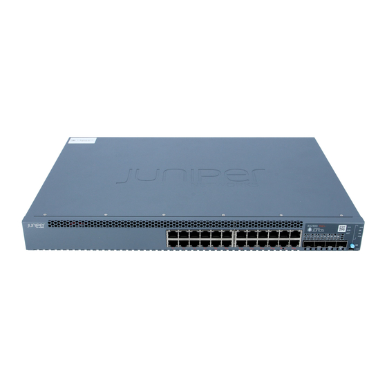
Juniper EX Series Quick Start Manual
Redundant power system
Hide thumbs
Also See for EX Series:
- User manual (280 pages) ,
- Complete hardware manual (194 pages) ,
- Manual (13 pages)
Table of Contents
Advertisement
Quick Links
Quick Start Guide
EX Series Redundant Power System
IN THIS GUIDE
Step 1: Begin | 1
Step 1: Begin
IN THIS SECTION
Mount The Rps | 2
To install and configure a Juniper Networks EX Series Redundant Power Supply (RPS), you need:
Two mounting brackets and eight mounting screws for rack mounting (provided)
One RPS cable per switch (one is provided, six is the maximum needed)
At least one EX-PWR3-930-AC power supply (one provided in a separate box)
Electrostatic discharge (ESD) grounding strap (not provided)
Advertisement
Table of Contents

Summary of Contents for Juniper EX Series
- Page 1 Mount the RPS | 2 Connect Power to the RPS | 2 To install and configure a Juniper Networks EX Series Redundant Power Supply (RPS), you need: Two mounting brackets and eight mounting screws for rack mounting (provided) One RPS cable per switch (one is provided, six is the maximum needed)
- Page 2 Phillips (+) screwdriver, number 1 (not provided) Screws to secure the chassis to the rack or cabinet (not provided) Mount the RPS Installing the RPS requires one person to lift the switch and a second person to secure it to the rack. Mount an RPS on two posts of a 19-in.
- Page 3 Locking lever Tighten captive screw. 5. Push the locking lever up to its highest position. 6. Using the screwdriver, tighten the locking lever screw. Each power supply can provide backup power for one switch, with a maximum of three switches concurrently supported by three power supplies.
- Page 4 The RPS powers up as soon as the first power supply is installed in the center slot. Install up to two additional power supplies with the power on (hot-swap)---be sure to connect a power cord to each power supply. Step 2: Up and Running IN THIS SECTION Connect Each Supported Switch to the RPS | 4 Installation is Complete | 5...
- Page 5 EX2200-24-4G REV: X1 750-026464 REV: X3 Mfg. Date 20090227 MAC: 00:23:9C:oE:19:00 MADE IN CHINA 4. If the RPS connector on the RPS chassis has a cover on it, remove the cover panel. 5. Connect the cable to the uncovered RPS connector. The RPS software starts configuring a connection as soon as both sides of the cable are connected.
- Page 6 Redundant Power System at https://www.juniper.net/documentation/. Permit only trained and qualified personnel to install or replace RPS components. Perform only the procedures described in this guide and the EX Series documentation. Other services must be performed only by authorized service personnel.
- Page 7 For technical support, see: http://www.juniper.net/support/requesting-support.html Juniper Networks, the Juniper Networks logo, Juniper, and Junos are registered trademarks of Juniper Networks, Inc. in the United States and other countries. All other trademarks, service marks, registered marks, or registered service marks are the property of their respective owners.


Need help?
Do you have a question about the EX Series and is the answer not in the manual?
Questions and answers