Table of Contents
Advertisement
Quick Links
Have this manual in your hands
using the FG Finder application.
WARNING
BEFORE THE INSTALLATION OF THE CONVERTER, WE RECOMMEND READING THE
INSTRUCTION MANUAL IN FULL TO PREVENT POSSIBLE DAMAGE TO THE PRODUCT.
PRODUCT INSTALLATION PRECAUTIONS:
Before performing any procedure on this instrument, disconnect it from the power grid;
Ensure that it has adequate ventilation, avoiding installation on control panels containing devices that
could cause it to operate outside its specified temperature range;
Install the product away from sources that may generate eletromagnetic disturbances, such as :
motors, contactors, relays, electrovalves, etc.;
AUTHORIZED SERVICES:
The installation and maintenance of the product must be performed only by qualified personnel;
ACCESSORIES
Use only Full Gauge Controls original accessories.
If you have any questions, please contact our technical support
THROUGH CONTINUOUS DEVELOPMENT, FULL GAUGE CONTROLS RESERVES THE RIGHT TO
CHANGE THE INFORMATION IN THIS MANUAL AT ANY TIME, WITHOUT PRIOR NOTICE.
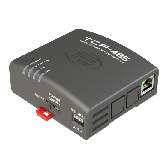
1. DESCRIPTION
The Serial/ Ethernet converter TCP-485 allows interconnecting Full Gauge controllers with the
supervisory software Sitrad through an Ethernet data network using the TCP/IP communication standard.
Currently, many companies have the Ethernet cabling ready in their facilities. With the TCP-485
converter, you can use the cabling already installed, making it unnecessary to create a new cabling for the
RS-485 network of the controllers.
The system consists of an Ethernet/RS-485 converter connected to the Ethernet network (be it by internet,
intranet, or directly to the computer) and Sitrad, which makes a direct TCP/IP connection to the Ethernet/
RS-485 converter, allowing communication with the controllers connected to it.
The converter transforms the RS-485 electrical standard used by the controllers into the TCP/IP
communications protocol used in the interconnection of computer networks.
2. APPLICATIONS
- Facilities without conditions to install new cabling, and with an Ethernet structure already in place.
- Centralize data collection from multiple remote locations onto one server without needing a computer
dedicated to each remote location.
NOTE: The TCP-485 converter is designed to work specifically with Full Gauge Controls instruments.
3. TECHNICAL SPECIFICATIONS
Converter power
Power supply provided with the converter
Operating temperature
Operating humidity
Number of instruments supported per
converter in the RS-485 network
Ethernet speed
Connections
Product dimensions
!
IMPORTANT INFORMATION:
If the ''LAN'' LED indicator in the RJ-45 connector does not light up upon connecting
the TCP-485 converter directly to the network adapter of the computer, you may
possibly need to use a crossover cable ( not supplied by Full Gauge) or connect the
computer and the converter via a HUB or a Switch.
!
STANDARD OPERATING MODE:
The factory's default operation of TCP-485 is DHCP Mode. See item 7 - Restoring the
default settings of the converter/ Changing IP Mode to switch the operation Mode.
!
IMPORTANT:
For a correct and robust installation of the RS-485 network, see item 9 -
Interconnecting the controllers and TCP-485.
TCP-485
SERIAL CONVERTER / ETHERNET
Supervisory
system
communication
External power supply 5.1 Vdc / 2A
Input - 100-240Vac (50/60Hz)
Output -5.1Vdc / 2A
0 to 50ºC / 32 to 122ºF
10 to 90% UR (without condensation)
32
10Mbps
-Connection type RJ-45 for connections to a PC using
the twisted-pair cable supplied along with the converter;
- One insulated RS-485 port to connect up to 32
instruments without the need of termination;
- Direct 80 cm Ethernet cable ( no crossover) supplied
along with the converted.
91,0 x 91,1 x 37,1 mm (WxHxP)
RS
485
Serial
Ethernet
4. WIRING DIAGRAM
LED Power - Power
indication LED
5. INSTALLATION AND OPERATION (DHCP MODE - DEFAULT
CONFIGURATION)
Connect interface terminals A,B and
instruments;
With the TCP-485 powered on, use an Ethernet cable to connect it to a router (switch) in the RJ-45
connectors according to the picture.
TCP-485
Source
R S - 4 8 5 n e t w o r k
reception indication LED
L E D S t a t u s -
Connection status
indication LED
R S - 4 8 5 n e t w o r k
transmission indication LED
Converter power
Reset key
Communication network
with RS-485 instruments
with the respective A,B and terminals on connecting blocks and
RJ45
Router
RS-485
MT-530
super
MT-530
Controller
super
Advertisement
Table of Contents

Subscribe to Our Youtube Channel
Related Manuals for Full Gauge TCP-485


Summary of Contents for Full Gauge TCP-485
- Page 1 - Direct 80 cm Ethernet cable ( no crossover) supplied instruments; along with the converted. With the TCP-485 powered on, use an Ethernet cable to connect it to a router (switch) in the RJ-45 connectors according to the picture. Product dimensions...
- Page 2 Step 2 : Selec t the option ‘’Use Ethernet communication’’. Then click on ‘’Configure Ethernet’’ button Step 3: The TCP-485 default name should show up. If not, the ‘’Refresh’’ button starts a new search for the below. converter in the network.
- Page 3 4 and click ‘’OK’’. If the user has the TCP-485 configured with a fixed IP, follow the steps below to connect it to a computer: - Check ‘’Use the following IP address’’ option and configure the fields with the following values: IP address : 192.168.2.126...
- Page 4 INCORRECT - Avoid splicing the cable; - Use the junction boxes provided by Full Gauge to connect the taps to the controllers. Besides facilitating the connection, they also have a protection function; - Avoid connections longer than 2 meters between the junction box and the controller;...
- Page 5 After this said year before the reseller network, the warranty shall continue to be executed if the instrument is sent directly to Full Gauge Controls. The products are warranted in case of defects in the workmanship, making them unsuitable or inadequate for the intended applications.
Need help?
Do you have a question about the TCP-485 and is the answer not in the manual?
Questions and answers