
Related Manuals for BFGoodrich TCAS791

Summary of Contents for BFGoodrich TCAS791
- Page 1 $5.00 U.S. Pilot’s Guide for the Traffic Alert and Collision Avoidance System I Model TCAS791...
- Page 2 TCAS I under an ARINC contract with the FAA. The completion of this contract represented yet another first for the TCAS791; it was the first TCAS I to be TSO’d, first to receive a full, unre- stricted STC, first to fly, and first to be delivered.
- Page 3 BFGoodrich Avionics Systems, Inc. No government or other contractual support or relationship whatsoever has existed which in any way affects or mitigates proprietary rights of BFGoodrich Avion- ics Systems, Inc. in these developments. Methods and apparatus disclosed herein may be subject to U.S.
- Page 4 All references in this guide to standby, look up/look down, altitude display modes (above, below, and normal), and transmitting from the ground are func- tions of all TCAS791 systems that have software version 1.3 or higher in their Transmitter Receiver Computer (TRC). Ignore these references if your TRC has an earlier version of software.
-
Page 5: Table Of Contents
Switch the Range and Altitude Display Mode ......... 2-13 Observe the Display ................. 2-14 Respond to Traffic Advisories ............2-15 Turn On the TCAS791 While in Flight ..........2-15 Post-Flight Instructions ................ 2-15 Turn Off the TCAS791 ..............2-16 Error Messages ..................2-16 TCAS Failed Screens ................ - Page 6 TCAS791 Table of Contents (Continued) Page Definition ..................3-3 When It’s Used ................3-3 Audio Inhibit, TCAS791 ................ 3-3 When It’s Used ................... 3-3 Audio Inhibit, GPWS ................3-4 TA Symbol Duration ................3-4 No-Bearing TAs ..................3-4 Other Factors That Affect the Display of Traffic Symbols ......3-4 Ground Target Filtering ................
- Page 7 Title Page TCAS791 Major Components ............. 1-1 Typical Screen on the CD605 Control Display Unit (CDU) ..1-2 TCAS791 Simplified Functional Diagram ........1-3 Protection Zones ................1-5 Controls and Indicators ............... 2-1 Display Ranges on the CD605 ............ 2-7 An Alternate Display w/Photocell &...
-
Page 8: Chapter 1 System Description
Collision Avoidance System (TCAS I). It monitors the airspace around your aircraft and advises the flight crew where to look for nearby transponder- equipped aircraft that may pose a collision threat. The TCAS791 is intended for use by regional airlines and corporate and general aviation aircraft. -
Page 9: Transmitter Receiver Computer (Trc)
TCAS791 Transmitter Receiver Computer (TRC) The TRC is the primary unit of the TCAS791. It contains the circuitry necessary to convert inputs into aural and visual advisories of intruding aircraft. The TRC can track up to 35 intruder aircraft simultaneously. If the TRC is tracking more than eight intruder aircraft, to reduce clutter, it will only display the eight most threatening ones. -
Page 10: Tcas791 Simplified Functional Diagram
429 output device may replace individual analog sensors for supplying radio and barometric altitude, and heading. 3. The TCAS791 may be installed on an aircraft with a fixed landing gear. The only operational difference occurs when you don’t have a radio altitude input. In that case, the TCAS791 defaults to using the highest TA sensitivity level regardless of your phase of flight. -
Page 11: Functional Description
System Description TCAS791 Functional Description The TCAS791 is an active system that operates as an air-to-air or ground-to- air interrogation device. The TCAS791 interrogates transponders in the sur- rounding airspace similar to ground-based radars. When replies to these inter- rogations are received, the responding aircraft's range, bearing, relative altitude, and closure rate are computed to plot traffic location and to predict collision threats. -
Page 12: Protection Zones
TCAS791 System Description Max. Display Range +9000 ft Intruder Aircraft Max. Display Range +2700 ft 4 nmi +1200 ft 0.55 nmi +800 ft 0.2 nmi +600 ft S e n siti vity Le ve l A 0 ft –600 ft... -
Page 13: Chapter 2 Operating Instructions
Operating Instructions Chapter 2 Operating Instructions Controls and Indicators Figure 2-1 calls out all the major controls and indicators for the TCAS791. Table 2-1 describes the TCAS791 controls and indicators. The number col- umn refers to items on figure 2-1. Notes... -
Page 14: Proximity Advisory
Operating Instructions TCAS791 Table 2-1. Controls and Indicators (Continued) Description Vertical Trend Arrow A vertical trend arrow indicates that the intruding aircraft is descending (down arrow) or ascending (up arrow) at a rate greater than 500 fpm. No arrow is shown for non-altitude reporting aircraft. - Page 15 The avionics dimming input from your aircraft controls the brightness of the light inside the test button on the CD605. Pressing the test button when in standby starts a TCAS791 self test. Pressing the test button repeatedly when not in standby toggles the altitude display mode in the following order: above, normal, below, normal, above, etc.
- Page 16 The selected range is indicated on the screen. Pressing and holding the range button when on the ground and not in standby changes the range and then switches the TCAS791 into standby. Pressing and holding the range button in flight has no effect other than changing the range.
- Page 17 The TCAS791 only displays data tags for altitude reporting aircraft. 15 Out of Range Traffic Advisory...
- Page 18 TCAS791 is turned on. The TCAS FAIL message may also appear on the alternate displays if there’s a TCAS failure, or if the TCAS791 fails a self test. It is also possible for an alternate display to display TCAS OFF instead of TCAS FAIL after a self test failure on the ground.
-
Page 19: Operating Instructions
TA aircraft is first detected. “ TCAS Test Passed” – This message is announced over the cockpit speakers or headset after the TCAS791 has passed an operator-initiated self test. “ TCAS Test Failed” – This message is announced over the cockpit speakers or headset after the TCAS791 has failed an operator-initiated self test. -
Page 20: An Alternate Display W/Photocell & Off-Center Aircraft Symbol
The procedures in this section are organized into tasks. You should perform all the tasks at least once after your TCAS791 is first installed; that way you will be familiar with how to use the features before you actually need to use them. -
Page 21: Preflight Instructions
2-4. The startup screen lists the firmware version numbers. After about 35 seconds, the TCAS791 will go into standby and the CD605 will display the standby screen as shown in figure 2-5. Figure 2-4. Startup Screen Figure 2-5. -
Page 22: Test Screen
Operating Instructions TCAS791 b. With the TCAS791 in standby, press the test button in one of the following two ways: 1) Press and release the test button. Pressing and releasing the test button allows the display to automatically revert to the standby screen after briefly display- ing the test screen and any status screens. -
Page 23: Switch Out Of Standby
If you hear the “TCAS Test Failed” message or see a TCAS Failed screen or a TCAS FAIL message, turn off the TCAS791 and sched- ule it for corrective maintenance as soon as possible. -
Page 24: Switch Into Standby
Figure 2-8. Standby Screen with Maintenance Code a. Press the range button. The TCAS791 will switch out of standby and into the above dis- play mode and 10 nmi range. (See figure 2-9.) An alternate dis- play may switch into some other altitude display mode and range. -
Page 25: Select The Range
Select the Range You can select from the available display ranges when your aircraft is on the ground and the TCAS791 is not in standby, or when your aircraft is in the air. The shortest range should typically be used during depar- ture, climbout, and descent to reduce traffic clutter. -
Page 26: Observe The Display
Monitor the activity of any traffic displayed. Keep in mind the follow- ing points when watching traffic on the display: • Traffic Prioritizing – The TCAS791 can track up to 35 intruder aircraft simultaneously, but to reduce clutter, it displays only the 8 most threatening aircraft of those tracked. -
Page 27: Respond To Traffic Advisories
In either case, you can turn off the TCAS791 as described below. You may want to Pilot’s Guide... -
Page 28: Turn Off The Tcas791
TCAS791 Figure 2-11. Normal Display Mode, 5 nmi Range leave the TCAS791 on after landing until you have had a chance to see if there’s a maintenance code on the CD605. A maintenance code will only show up when you’re on the ground, and only on the CD605. (Refer to the section on maintenance codes later in this chapter.) -
Page 29: Barometric Input Failures
TCAS791. If the TCAS Failed/Barometric Input screen appears, do not turn off the TCAS791. When the baromet- ric altitude input is restored, the TCAS791 will automatically return to normal operation. -
Page 30: Chapter 3 Principles Of Operation
±800 ft relative altitude within 20–30 sec. of CPA Sensitivity Level A Sensitivity Level B Having a radio altimeter means having a radio altimeter that is compatible with the TCAS791, wired to the TCAS791, and providing valid altitude information. Pilot’s Guide... -
Page 31: Sensitivity Levels
Figure 3-1. TA Protection Zones if Your Aircraft Has a Radio Altimeter Sensitivity Levels The TCAS791 uses one of two sensitivity levels, A or B, to determine when to display a TA. Having two sensitivity levels allows the TCAS791 to reduce the number of nuisance TAs during takeoff and landing (sensitiv- ity level A), and to maximize the detection of TAs during the cruise phase of your flight (sensitivity level B). -
Page 32: When It's Used
The corresponding TA symbols will still be displayed. When It’s Used The TCAS791 uses this audio inhibit feature in the following situa- tions: • Your aircraft has a radio altimeter and you’re below 400 ft AGL. -
Page 33: Audio Inhibit, Gpws
TA Symbol Duration The TA symbol remains on screen for a minimum of 8 seconds even if the intruder aircraft no longer meets the TA criteria as long as the TCAS791 continues to track the aircraft. No-Bearing TAs Intruder aircraft detected only with the omnidirectional antenna will not be displayed unless they become TA’s. -
Page 34: Chapter 4 Display Interpretation
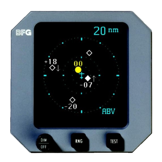
Figure 4-1. Traffic Advisory and Other Traffic Out of Range Traffic Advisory: Intruder aircraft at 11 o’clock, more than 5 nmi away, 300 ft above you, descending at a rate greater than 500 fpm Figure 4-2. Out of Range Traffic Advisory Pilot’s Guide TCAS791 Pilot’s Guide... -
Page 35: Bearing Traffic Advisory
Display Interpretation TCAS791 No-Bearing Traffic Advisory: Intruder aircraft 1.1 nmi away, 1,000 ft below you, climbing at a rate greater than 500 fpm Figure 4-3. No-Bearing Traffic Advisory No-Bearing No-Altitude Traffic Advisory: Intruder aircraft 0.7 nmi away (no bearing or altitude available) Figure 4-4. -
Page 36: Tcas Failed Screen
TCAS791 Display Interpretation This message is displayed any time the TCAS791 detects a failure. It also appears if the TCAS791 fails the operator-initiated self test. If this message remains on the screen for more than 5 minutes, turn off the TCAS791. -
Page 37: Out Of Standby On The Ground
Display Interpretation TCAS791 Instructions for switching into standby and stopping TCAS processing (press and hold the RNG button). This message will only appear when your aircraft is on the ground. Figure 4-9. Out of Standby on the Ground Pilot’s Guide... -
Page 38: Chapter 5 Specifications
Specifications Chapter 5 Specifications Tables 5-1 through 5-4 list the specifications for the major components of the TCAS791. Specifications are subject to change without notice. Table 5-1. Transmitter Receiver Computer (TRC) Specifications Part Number Definition: 805-10001-004 – TRC791 805-10001-024 – TRC791A 805-10001-025 –... - Page 39 Specifications TCAS791 Table 5-2. CD605 Control Display Unit Specifications Part Number Definition: 805-10007-005 – 2-button, white/cyan/amber CRT, black faceplate, +5 V backlighting 805-10007-006 – 2-button, white/cyan/amber CRT, gray faceplate, +5 V backlighting 805-10007-007 – 2-button, white/cyan/amber CRT, black faceplate, +28 V backlighting 805-10007-008 –...
- Page 40 TCAS791 Specifications Table 5-4. NY152 L-Band Antenna Specifications Part Number: 805-10005-001 Height: 2.68 in (6.70 cm) Weight: 0.3 lb (0.14 kg) Speed: Rated to 600 knots (0.9 Mach) @ 25,000 ft Frequency: 960-1,220 MHz TSO Category: C66b, C74c Environmental Category:...
-
Page 41: Chapter 6 Warranty Information
Chapter 6 Warranty Information Introduction The TCAS791 is warranted for 2 years from the date of installation (not to exceed 30 months from the date of shipment from BFGoodrich Avionics Sys- tems, Inc.) subject to the following limitations. Warranty Statement BFGoodrich Avionics Systems, Inc. -
Page 42: Related Policies And Procedures
TCAS791 Related Policies and Procedures a. If the original registered owner of a TCAS791 sells the aircraft in which the TCAS791 is installed during the warranty period, the remaining war- ranty may be transferred. Written notification of the transaction must be... - Page 43 Part Number _______________________________________________ Serial Number ______________________________________________ Note To ensure that a new or repaired TCAS791 meets the FAA TSO, gets foreign government approval, and meets BFGoodrich Avi- onics Systems, Inc. performance standards, your TCAS791 must be installed and tested by a BFG-authorized TCAS791 dealer.
- Page 44 009-10025-001 (Rev. F, 3/9/99) BFGoodrich Avionics Systems, Inc. TCAS791 5353 52nd Street, S.E. P .O. Box 873 Grand Rapids, MI, 49588-0873 USA (800)253-9525...
Need help?
Do you have a question about the TCAS791 and is the answer not in the manual?
Questions and answers