
Related Manuals for BFGoodrich SKYWATCH HP SKY899

Summary of Contents for BFGoodrich SKYWATCH HP SKY899
- Page 1 $12.00 U.S. $12.00 U.S. Pilot’s Guide Pilot’s Guide for the for the Traffic Alert/Advisory System Traffic Alert/Advisory System Model SKY899 Model SKY899...
-
Page 2: Chapter 6, Specifications
™ Eyes That Never Blink Early Traffic Alert/Advisory Systems In the early days of flight, pilots were equipped with all they needed for effective collision avoidance–a sharp pair of eyes. But increasing traffic at higher speeds led to the development raffic lert and ollision... - Page 3 Goodrich Avionics Systems, Inc. No government or other contractual support or relationship whatsoever has existed which in any way affects or mitigates proprietary rights of BFGoodrich Avionics Systems, Inc. in these developments. Methods and apparatus disclosed herein may be subject to U.S. Patents existing or applied for.
- Page 4 Safety Summary These warnings and cautions appear later in this guide and are repeated here for emphasis: To avoid power surges that could damage the and the SKY899 CAUTION optional , start your engines before turning on the WX-1000 SKY899 page 3-1 If the is in...
-
Page 5: Table Of Contents
Table of Contents Section Page List of Illustrations ........v List of Tables..........vi Abbreviations & Acronyms......vii Chapter 1, System Description ....1-1 General Description ..............1-1 Transmitter Receiver Computer (TRC) ........1-2 Directional Antenna ..............1-2 Display ..................1-3 Interaction of Major Components .......... - Page 6 Table of Contents (continued) Section Page Chapter 4, Principles of Operation ....4-1 Introduction ................4-1 Sensitivity Levels ................ 4-1 Sensitivity Level A ..............4-1 Sensitivity Level B ..............4-3 Audio Inhibit, SKY899 ............... 4-5 Audio Inhibit, GPWS, EGPWS, or TAWS ........4-5 TA Symbol Duration ..............
-
Page 7: List Of Illustrations
Controls & Screen Elements in Standby ..........2-1 Controls & Screen Elements in Operating Mode ......... 2-2 Vertical Display Mode Indicator Lamps ..........2-6 BFGoodrich Screen ................3-1 Standby Screen .................. 3-2 In-Flight Traffic Screen............... 3-2 Failed Screen ..................3-2 Test Screen .................. - Page 8 List of Tables Table Title Page Fourteen Situations in Which a Traffic Advisory Will Occur ....4-2 TRC899 Specifications ..............6-1 BFG WX-1000/SKY497 Display Specifications ........6-3 NY164 Directional Antenna Specifications (for TAS installations only) ..............6-4 NY156 Directional Antenna Specifications ( required for TCAS I installations, optional for TAS ) .......
-
Page 9: Abbreviations & Acronyms
Aeronautical Radio, Inc. Air Traffic Control ATCRBS Air Traffic Control Radar Beacon System Air Transport Indicator Air Traffic Management BFGoodrich BFGAS BFGoodrich Avionics Systems, Inc. Below Comm Communication Closest Point of Approach Cathode Ray Tube EFIS Electronic Flight Instrument System... - Page 10 Abbreviations & Acronyms (continued) Message Navigation Nautical Miles (on the display) Nautical Miles (in the text) Normal Operate Other Traffic Proximity Advisory Part Number Revision Radar Graphics Computer RTCA Requirements & Technical Concepts for Aviation Sensitivity Level A Sensitivity Level B Secondary Surveillance Radar Standby Traffic Advisory...
-
Page 11: Chapter 1, System Description
C h a p t e r 1 System Description General Description raffic lert/ dvisory ystem, model ® SKYWATCH HP T , from oodrich vionics ystems, nc. ( ) can be SKY899 installed as a raffic lert and ollision voidance ystem ) or as a raffic... -
Page 12: Transmitter Receiver Computer (Trc)
TRC & Antenna Chapter 1 – System Description When installed as a , the can share a model SKY899 monochrome display ( WX-1000/SKY497 P/N 78-8060-5900-8 ® ) with a model using a remote BFG STORMSCOPE WX-1000 tormscope mode switch. As a , the SKYWATCH/S SKY899... -
Page 13: Display
Chapter 1 – System Description Display Display The display is a -inch ransport ndicator ( ) unit 3-ATI with a high resolution, green monochrome athode ) display. The bezel contains four momentary contact push-button switches and an on/off/brightness knob. The display provides control and display functions for the SKY899 (installed as a... -
Page 14: Interaction Of Major Components
Interaction of Major Components Chapter 1 – System Description Interaction of Major Components Figure shows how the major components of the SKY899 connect to each other and to other aircraft systems. Notes on Figure 1-4: 1. The optional radio altitude input affects the audio SKY899 inhibit feature, the ground intruder filtering feature, and... -
Page 15: System Block Diagram
Chapter 1 – System Description System Block Diagram Intruder Aircraft Transponder Transponder ADS-B Squitter Interrogations Replies Broadcasts SKY899 Directional Antenna Transponder Transponder ADS-B Squitter Interrogations Replies Broadcasts Radio Altimeter or Barometric Altitude Radio Altitude Flight Data Encoding Altimeter Computer System Software (Optional) Air Data Computer Updates... -
Page 16: Features
Features Chapter 1 – System Description ing aircraft. The then predicts collision threats and SKY899 plots the eight most threatening aircraft locations on the display. Figure shows the vertical display modes (look up, SKY899 look down, normal, and unrestricted). The figure also shows the traffic zones around your aircraft and the traffic symbols that appear on the display when intruding aircraft enter one of those zones. -
Page 17: Vertical Display Modes And Traffic Zones
Chapter 1 – System Description Traffic Zones Diagram 15 nmi 15 nmi +9900 ft +9900 ft (OT) 15 nmi +9000 ft (OT) Intruder Aircraft 15 nmi +2700 ft 4 nmi +1200 ft 0.55 nmi +800 ft 0.2 nmi +600 ft S e n si tiv ity Le ve l A 0 ft –600 ft... - Page 18 Features Chapter 1 – System Description Features – Continued • Performs automatic and operator-initiated self tests • Offers a high-resolution, green monochrome, display for installations • Transmits interrogations from the ground (if desired) as well as from the air • Shares a display with the tormscope (if desired) WX-1000...
-
Page 19: Chapter 2, Controls & Indicators
C h a p t e r 2 Controls & Indicators Introduction This chapter describes the controls and indicators SKY899 including the controls, indicators, and symbols on the display, discrete controls and indicators, and aural announcements. Controls, Indicators, & Symbols Figures and the following paragraphs describe the controls, indicators, and symbols. -
Page 20: Controls & Screen Elements In Operating Mode
On-Screen Elements Chapter 2 – Controls & Indicators Range Power/ Rings Brightness Control Knob Off-Screen Data Tag Traffic Advisory ( Traffic Advisory (TA) Own Aircraft Vertical + 10 Other Traffic Trend Arrow Message Operating Button Mode Button Message Label for Op Indicator Mode Button Vertical... -
Page 21: Standby Screen
Chapter 2 – Controls & Indicators Buttons & On-Screen Elements located at a position on the screen that indicates the relative bearing and range of the intruder aircraft. In general, the issues a when it detects an SKY899 intruder aircraft within seconds of a possible collision, or within a nmi horizontal radius and a ±... - Page 22 Buttons & On-Screen Elements Chapter 2 – Controls & Indicators Vertical Display Mode Indicator This indicator displays the name of the currently selected vertical display mode: (above/look up), (below/look down), (normal), or (unrestricted). The indicator does not appear when the is in standby.
-
Page 23: Controls Required For The Stormscope Option
Chapter 2 – Controls & Indicators for Stormscope represents an intruder aircraft that does not generate a , but which is within a horizontal range of nmi and a relative altitude of ± 1200 Own Aircraft This symbol represents your aircraft’s relative position and heading. -
Page 24: Controls & Indicators For An Alternate Display
Alternate Display & Aural Announcements Chapter 2 – Controls & Indicators WX-1000 Maintenance Switch This (not supplied) remote toggle switch (normally installed in the avionics bay near the processor) has a ormal position and an WX-1000 verride ( maintenance) position. It should only be WX-1000 moved to the verride position when the... -
Page 25: Chapter 3, Operating Instructions
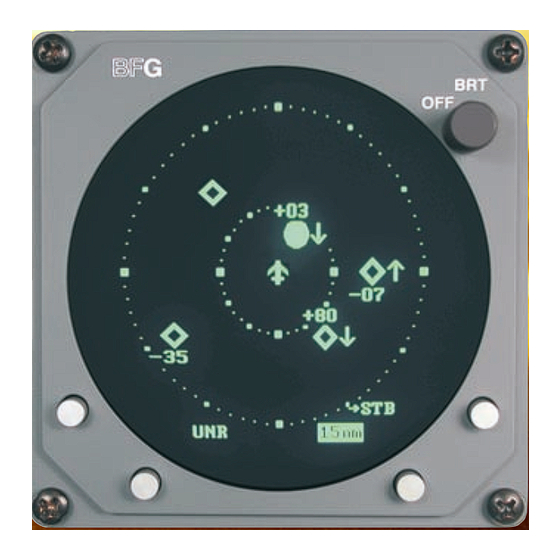
BFGoodrich Avionics Systems,Inc. craft is in the air, the traffic screen appears set on the display range and the normal vertical display mode (figure Figure 3-1. BFGoodrich Screen SKY899 Pilot’s Guide... -
Page 26: Failed Screen
Turn on the SKY899 Chapter 3 – Operating Instructions + 1 0 SKY899 Standby - 2 6 TEST 6 nm Figure 3-2. Standby Screen Figure 3-3. In-Flight Traffic Screen If the passes the test and your aircraft does not have a SKY899 squat switch, the standby screen (figure ) appears. -
Page 27: Run The Operator-Initiated Self Test
Chapter 3 – Operating Instructions Run the Self Test Run the Operator-Initiated Self Test It is recommended, but not required that you should run the operator-initiated self test before the first flight of the day (or as specified in your ircraft light anual [... -
Page 28: Change The Display Range
Change the Display Range Chapter 3 – Operating Instructions switches SKY899 out of standby into the above display + 1 0 mode and range (figure If your aircraft has a squat switch and you + 9 4 don’t manually switch out of standby, the automatically SKY899...
Need help?
Do you have a question about the SKYWATCH HP SKY899 and is the answer not in the manual?
Questions and answers