Table of Contents
Advertisement
Advertisement
Table of Contents
Troubleshooting

Related Manuals for Vertical Express HD98

Summary of Contents for Vertical Express HD98
- Page 1 HD98 Door Operator with Owner’s Service Tool (OST)
- Page 2 Every attempt has been made to ensure that this documentation is as accurate and up-to-date as possible. However, Vertical Express assumes no liability for consequences, directly or indirectly, resulting from any error or omission. The material contained herein is subject to revision. Please report any problems with this manual to Vertical Express, P.O.
-
Page 3: Table Of Contents
HD-98 Door Operator with OST Contents Contents Safety Precautions ..............3 General Safety . - Page 4 Replacement Parts ..............39 Vertical Express...
-
Page 5: Safety Precautions
Safety Precautions HD-98 Door Operator with OST Safety Precautions IMPORTANT! Read this page before any work is performed on elevator equipment. The procedures contained in this manual are intended for the use of qualified elevator personnel. In the interest of your personal safety and the safety of others, do not attempt any procedure that you are not qualified to perform. -
Page 6: Mechanical Safety
When Power Is On To avoid personal injury, do not touch exposed electrical connections or components while power is Mechanical Safety Elevator Industry Field Employees’ Safety Handbook See the for mechanical equipment safety information on installation and service. Vertical Express... -
Page 7: Arrival Of Equipment
• “Peanuts” and styrofoam are unacceptable packing materials. Note: Refer to the Vertical Express Replacement Parts Catalog to order extra static bags and shipping cartons for each card. Failure to adhere to the above guidelines will VOID the card warranty! - Page 8 HD-98 Door Operator with OST Contents Contents This page intentionally left blank. Vertical Express...
-
Page 9: Overview
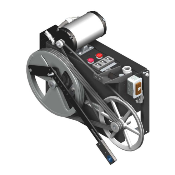
HD-98 Door Operator with OST Overview Overview The following is a list of the major components of a door operator including a description of their functions, an overview of some of the critical adjustments, and maintenance information. See Figure 1 on page 8. •... -
Page 10: Mechanical Installation And Adjustment
See Figure 2 on page 9. a. Loosen the two bolts on the idler arm, and turn the locknut on the adjustment screw (located at the end of the idler arm). b. Securely tighten the idler arm bolts and the locknut. Vertical Express... -
Page 11: Mounting The Door Operator
HD-98 Door Operator with OST Mechanical Installation and Adjustment Preparing the Door Operator (continued) Idler Arm Locknut Figure 2 - Locknut Adjustment Screw 8. Check and adjust as necessary the tension on the single V belt between the motor sheave and jack shaft sheave: a. - Page 12 Bearing Spacer Drive Washers Support Door Bearing Strut Door Operator Spacer Operator Support Rear Frame Drive Arm Support Door Support Clip Panel Connecting Detail A Detail B Detail C Detail D Figure 3 - Mounting the Door Operator Vertical Express...
-
Page 13: Setting The Stroke
HD-98 Door Operator with OST Mechanical Installation and Adjustment Setting the Stroke Notes: • The two cap screws securing the intermediate arm to the pivot arm should be loose when set- ting the stroke. • Fully Open Position - The point where the doors are flush with or slightly recessed behind the open door jamb. -
Page 14: Adjusting The Drive Arms
Note: Once the stroke has been properly adjusted, check to ensure that the two cap screws in the adjustable arm and the two cap screws holding the pivot arm to the intermediate arm are securely tightened. Vertical Express... - Page 15 HD-98 Door Operator with OST Mechanical Installation and Adjustment Adjusting the Drive Arms (continued) Spacer Plate Door Open Pivot Pivot Arm Adjustable Intermediate Adjustable Intermediate Drive Pivot Mechanical Point Stop–door Open Adjustable Bearing Spacer Adjustable Point B is center Intermediate of Drive Wheel Spacer Plate...
-
Page 16: Setting The Mechanical Stops
When power is turned ON or the door reset button on the door card is pushed, the watchdog LED on the door card should come on for 2 seconds, turn OFF, then come back ON and remain ON. Vertical Express... -
Page 17: Door Card Configuration
HD-98 Door Operator with OST Adjustment Limit Setting and Direction Check (continued) Gate Switch Magnet Door Card Magnetic Reset FUSE F2 Sensor Button 8” Magnet centers MUST Magnetic line up with the centers Sensor of the magnetic sensors Watchdog LED FUSE F1 Figure 6 - Door Operator Limit Cams and Door Card Door Card Configuration... -
Page 18: Door Setup
Note: The doors will not scan with a value other than zero (0) in E56. 4. View E56 to verify that a value was learned. 5. Use the OST to issue the WRT Command. Vertical Express... -
Page 19: Nudging Duty
HD-98 Door Operator with OST Door Setup Nudging Duty Notes: • If there is a safety edge or photo-eye failure, the doors will run closed at nudging duty. • If an electronic safety edge is used, the doors can operate at nudging duty on Fire Service. •... -
Page 20: Final Door Adjustments
8. E07 (Acceleration Rate To Open High Speed) - Change E07 to a value that allows the door to move smoothly but rapidly to high speed. The acceleration rate increases as the E07 value is increased. Vertical Express... -
Page 21: Close Adjustments Procedure
HD-98 Door Operator with OST Door Setup Close Adjustments Procedure To avoid mechanical damage to the doors when increasing Open and Close High Speed, do NOT make drastic changes. 1. E12 (Close High Speed) - Change E12 to a value that gives the desired close high speed. The close high speed increases as the E12 value is increased. -
Page 22: Torque
Use the UP or DOWN arrow keys to change values within the allowed range. 7. When the adjustment value is correct, press ENTER. The OST displays "Hit ENTER to WRT." 8. To save the parameter, press ENTER. Vertical Express... -
Page 23: Door Adjustment Diagrams
HD-98 Door Operator with OST Door Setup Door Adjustment Diagrams Doors Closed (DCL) Doors Open (DOL) E19 (High Speed Clamp) Range = 0-100 E10 (Open Backlash Time) (increments of 8, avoid setting over 50) Range = 1-100 (setting must be at least 8 more than E04) E04 (Open High Speed) Range = 1-127 E11 (Smooth Turnaround) -
Page 24: Setting The Gate Switch
Be sure that the gate switch leaf contacts do not rub on the thin portion of the plastic disk during normal operation. Shorting Bar Gate Closed Switch Gate Switch Leaf Contacts Figure 10 - Gate Switch Final Security Recheck all bolts, cap screws, cam hex screws, and belt tensions for proper tightness Vertical Express... -
Page 25: Diagnostics
HD-98 Door Operator with OST Diagnostics Diagnostics Electronic Door Operator Adjustments • Use the OST to access the electronic door adjustments. • Edit adjustments as required. • Use the WRT command to save adjustments to flash memory. Adjustment Range Default Definition Clear Fault Buffer - When set to 1, the electronic door fault buffer is cleared. - Page 26 DCL (door close limit). This count is automatically set on power-up when the saved value in the CPU memory is zero. The doors will begin the set-up count from DOL. If the doors are not on DOL, they will move to DOL and then close, counting pulses until their arrival at DCL. Vertical Express...
-
Page 27: Electronic Door Faults
HD-98 Door Operator with OST Diagnostics Electronic Door Faults • The door fault buffer can store a maximum of 30 door faults. Each fault is different regardless of the number of times it occurs. • Use Adjustment E03 (Clear Fault Buffer) to clear door faults. •... - Page 28 DO ADJ-13 is set too low. The high speed clamp should be set 8 above the level at which speed clamping occurs. • Door Speed has increased. This can be caused by a defective door operator card or by physically pushing the doors until overspeed occurs. Vertical Express...
- Page 29 HD-98 Door Operator with OST Diagnostics Fault Code Description / Causes / Solutions (Continued) 327 / 627 Closed Overspeed Error - Indicates that the closing door speed exceeded the setting of the high speed clamp E19. • High Speed Clamp (E19) is set too low. The high speed clamp should be set 8 above the level at which speed clamping occurs.
-
Page 30: Troubleshooting
The car door switch closes 1” from Fully Closed. Door watchdog operation will recycle the doors if the interlocks (DR or DCL) do not make up. When servicing, be prepared for the doors to cycle. To disable watchdog operation, place the car on Inspection Operation. Vertical Express... -
Page 31: Troubleshooting Guide
HD-98 Door Operator with OST Troubleshooting Guide Troubleshooting Guide For assistance, please call 1-866-HELP-TKE. Problem Possible Causes or Solutions Doors move sluggish and jerky. 1. Worn or loose V belts. 2. Motor sheave loose on shaft. 3. Poor mechanical adjustment of doors. 4. - Page 32 DOC2 DOC1 DGND Test Point IFB Test Point P3.3 Test Point P5 Test Point Watchdog LED P5V LED Manual Door Close Button Manual Door Open Button Reset Button DCL LED DOL LED Figure 11 - Door Operator Card Vertical Express...
-
Page 33: Phasing J2, Motor Leads, And Encoder Connections
HD-98 Door Operator with OST Troubleshooting Guide Phasing J2, Motor Leads, and Encoder Connections For the door operator to function correctly, the door motor armature, the J2 jumper, and the Phase A and Phase B sensors must be in phase with each other. To reverse motor direction, the wiring is designed to allow removal or installation of the J2 jumper. -
Page 34: Phase A And Phase B Motor Sensor Check
If P5V LED is not ON: a. Check the Fuse F3 on the door operator card. b. Verify that the P24IN faston and DOC3 are connected to the door card. Verify whether P24 is present in the door operator. Vertical Express... -
Page 35: Se, Ee, Dr, And Wdp
HD-98 Door Operator with OST Troubleshooting Guide Door Operator I/O Checks (continued) 3. If the WD LED is ON, press the MDO button. The doors should move in the open direction. • If the doors do not move, or if the doors move in the closed direction: a. -
Page 36: Door Communications Troubleshooting
Use a volt meter on DC to measure voltage on the PSC and NSC terminals on the TCID Card (located at the top of the controller). Note: A correct measurement is 2.25vdc to 2.75vdc (meter-averaged values of proper 5vdc communications packet activity). b. If the correct measurement is not seen, replace the EDR2. Vertical Express... - Page 37 HD-98 Door Operator with OST Door Communications Troubleshooting Door Communications Troubleshooting (continued) CON23 DOC2 DOC1 188E CPU Card EDR2 Door Operator Card TCID Card Figure 13 - Connectors on Door Communications Cards Printed in USA November, 2011...
-
Page 38: Wiring Diagrams
Wiring Diagrams HD-98 Door Operator with OST Wiring Diagrams Vertical Express... - Page 39 HD-98 Door Operator with OST Wiring Diagrams Wiring Diagrams (continued) A17.1 Compliant Front Car Top Inspection Station Wiring Diagram Printed in USA November, 2011...
-
Page 40: Maintenance
6. Check the operation of the gate switch, and make sure that it is adjusted per code. 7. Use a burnishing tool or clean rough paper, and clean the gate switch contacts (if necessary). 8. Replace the door operator cover. 9. Check for excessive bearing wear. Vertical Express... -
Page 41: Replacement Parts
HD-98 Door Operator with OST Replacement Parts Replacement Parts 3001AD_ HD-98 Door Operator .250 SECTION A-A Printed in USA November, 2011... - Page 42 Replacement Parts HD-98 Door Operator with OST 3001AD_ HD-98 Door Operator (continued) Vertical Express...
- Page 43 HD-98 Door Operator with OST Replacement Parts 3001AD_ HD-98 Door Operator (continued) ITEM PART NO. PRINT NO. DESCRIPTION 591BH1 115 VDC, 1/6 H.P. w/Optical Sensor Assembly 9820966 750DB1 Sheave, Motor 124050 Tap Bar, Arm 9723997 123992 Arm, Adjustable 9749470 77920 Belts, Drive 9876686 67668...
- Page 44 Cover, Gate Switch 9772637 171BJ1 Switch, Leaf, Gate 9741227 141222 Holder, Magnet 9741252 141251 Magnet, Cam 171CM1 Switch, Toggle 9782527 108252 Bell, Emergency Alarm 9736254 177AM1 Alarm, Audible Signal, 12V 9763754 141787 Stand-off, Card, Locking 786AJ1 Spacer, Card Vertical Express...
- Page 46 P.O. Box 2019 Memphis, TN 38101 Tel: (866) 448-3789 (toll-free) Fax: (901) 261-1807 www.verticalxpress.com All illustrations and specifications are based on information in effect at the time of publication approval. Vertical Express reserves the right to change specification or designs and to discontinue items without prior notification or obligation. v.Y.m. Copyright © 2011 Vertical Express...
Need help?
Do you have a question about the HD98 and is the answer not in the manual?
Questions and answers