Table of Contents
Advertisement
TECHNICAL INFORMATION / INSTALLATION INSTRUCTIONS
Compact Solar Drainback System SECUSOL
Operational Safety and Low Maintenance
When the pump is not operating, there is no solar fluid
present in the collectors. Therefore the solar fluid and any
downstream system components are protected against
detrimental effects from overheat. Unwanted gravitational
forces as well as operational faults due to air pockets are
eliminated. A service intensive membrane expansion ves-
sel, air bleeds and check valves are not required. Operati-
on with common anti-freeze solar fluid prevents potential
frost damage.
High Yield Thanks To:
High transparency anti reflection glass
●
Single surface absorber with selective vacuum coating
●
Solid insulation of individual components
●
Simplified Installation and Start-Up
Pre-assembled unit of storage tank, solar controller and
●
solar circulator, including all safety components.
Flexible copper double-pipe with only 12mm cross
●
section, for simple and time saving piping (supplied by
Wagner & Co).
No expansion vessel and hence no setting of pre-pres-
●
sure required.
Very simple flushing and filling
●
No venting of solar circuit required
●
Installation, startup and maintenance of the SECUSOL
solar thermal installation are intended to be carried out
by trained professionals only, e.g. in line with SRCC Stan-
dard OG-300 installation guidelines or NABCEP certifica-
tion. They have to be licensed, must be familiar with the
IAPMO Uniform Solar Energy Code and must conform
to applicable federal, state and local regulations, codes,
standards and meet all legal requirements related to the
installation of solar hot water systems as well as plumbing,
electrical wiring and roof works.
Content
1
1.1
1.2
1.3
2
2.1
2.2
2.3
2.4
2.5
2.6
Solar thermal / Collectors
EN-USA_SECUSOL_TI-MA-111013-1121R800
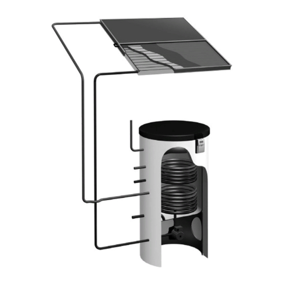
Figure 1 SECUSOL-System
3
3.1
3.2
3.3
3.4
3.5
2
3.6
2
3.7
8
3.8
14
4
16
4.1
16
4.2
16
4.3
17
5
17
6
18
7
18
8
19
19
20
24
29
29
29
31
35
36
36
36
36
38
38
39
40
1
Advertisement
Table of Contents

Related Manuals for Wagner & Co SECUSOL

Summary of Contents for Wagner & Co SECUSOL
-
Page 1: Table Of Contents
Very simple flushing and filling ● No venting of solar circuit required ● Installation, startup and maintenance of the SECUSOL Figure 1 SECUSOL-System solar thermal installation are intended to be carried out by trained professionals only, e.g. in line with SRCC Stan- dard OG-300 installation guidelines or NABCEP certifica- tion. -
Page 2: Technical Information
1 Technical Information 1.1 Technical Data Table 1 Technical Data SECUSOL SECUSOL SECUSOL Features 250-1 250-2 350-2 Solar collectors Type EURO C20 AR-M EURO L42 or EURO C20 AR-M EURO C20 AR-M EURO L42 Gross area / aperture area sq ft (m²) 28.1 sq ft (2.61 m²) / 24.2 sq ft (2.25 m²) /... - Page 3 76.10 in/1933 mm EURO L42 HTF 84.69 in/2151 mm EURO C20 AR M Figure 2 Dimensions of solar collectors EURO L42 (upper image) and EURO C20 AR-M (lower image). Throughout this document and all other Wagner & Co do- cumentation the term „flow“ refers to the hot, outgoing pipe leg, while the term „return“...
- Page 4 Figure 3 Dimensions SECUSOL 250 solar storage tank; (1) Flange with sacrificial anode; Dimensions of cylinders are without insulation. SECUSOL 250 is available with and without backup heat exchanger (upper coil). The image shows the version with upper coil. The version without upper coil does not feature the connections 5 and 6.
- Page 5 1" NPT(M) 3/4" NPT(F) 3/4" NPT(M) 1" NPSM (F) 3/4" NPT(M) SECUSOL 350 3/4" G 1" NPT(M) 11.81 in 300 mm 23.62 in (600 mm) Figure 4 Dimensions of SECUSOL 350 solar cylinder (without insulation). (1) Flange with sacrificial anode EN-USA_SECUSOL_TI-MA-111013-1121R800...
- Page 6 On roof 76.1 in / 1933 mm EURO L42 >160 in / 4060 mm Free standing setup >160 in / 4060 mm 76.1 in / 1933 mm EURO L42 Figure 5 Connection options for the EURO L42 for on-roof and free-standing installation, with sensor positions, dimensions of the collector field and racking system.
- Page 7 System in operation Figure 7 Design principle of the SECUSOL system. Left hand side: When in idle state, the collector loop and the collctor are filled with air (light-coloured lines). The solar fluid (darker lines) is located in the heat exchanger. Right hand side: When the system is in operation the air is pushed into the upper loops of the heat exchanger by the rising solar fluid.
-
Page 8: Scope Of Supply
1 plug 1" NPSM (fixed to pallet), for closing the storage socket Collector adapter set 1) For details see Table 5 and Figure 8 US Secusol serial connection set US Secusol parallel connection set Roof anchor / rafter bracket (only for on-roof installation) 1) Minimum no., actual no. - Page 9 Figure 8 Scope of supply of the SECUSOL storage cylinder shown for the 250 l- (see table 5 for a position number legend). EN-USA_SECUSOL_TI-MA-111013-1121R800...
- Page 10 Set for single collector Note The roof brackets shown throughout this document are of the type A1 Pro+, specifically developed for common North-American asphalt shingle roofs. For installation details refer to the separate instructions coming with the roof brackets. Other roofing types require different roof anchors.
- Page 11 Collector installation set for horizontal installation, one above the other Note The roof brackets shown throughout this document are of the type A1 Pro+, specifically developed for common North-American asphalt shingle roofs. For installation details refer to the separate instructions coming with the roof brackets.
- Page 12 Collector installation set for horizontal installation, next to each other Note The roof brackets shown throughout this document are of the type A1 Pro+, specifically developed for common North-American asphalt shingle roofs. For installation details refer to the separate instructions coming with the roof brackets.
- Page 13 Set for free standing rackets Figure 12 Set for free standing setup Table 9 Free standing racks, scope of supply Single collector; 2 Collectors next to each other; order no. 192 001 00 order 2 x no. 192 001 00 Position Components Quantity Pre-assembled racking triangle Hexagonal head screw M8 x 40 Nut M8 with locking teeth Collector clamp – lower part Collector clamp –...
-
Page 14: Accessories
1.3 Accessories Table 10 Accessories Description Part no. Euro collector carrying handles (2 pieces) 192 040 60 Thermostatic Mixing Valve ¾" 150 303 83 Twin Cu solar circuit pipe comprised of insulated double copper pipe 150 300 67 2 × 12 mm with integrated temperature sensor line, 15 m coil Oval clamp set for for Twin-Cu 150 301 18 Solar circuit insulation: flexible foam insulation 13x12 for single pipes (Aeroflex),... - Page 15 Table 10 Accessories Description Part no. US Secusol parallel connection set 150 303 93 US Secusol serial connection set 192 040 64 Collector adapter set 1/2“-12mm 192 040 62 US_Secusol Cx-threaded elbow connection set 12mm 819 110 99 4 x straight compression fitting 12mm...
-
Page 16: General Safety Notes
2 General Safety Notes 1. Inspect for and remove frost and other slipping hazards before getting onto roof surfaces. 2.1 Symbols 2. Cover and secure all skylights and openings, or install guardrails to keep workers from falling through the The following symbols are used throughout these inst- openings. -
Page 17: Qualification Of The Installer
Conformity The SECUSOL solar energy system and its components were designed and manufactured in accordance with cur- rent European Union and United States laws and regula- tions. The system and its components are in compliance with SRCC OG 100, IAPMO and NSF testing and/or certi- fication standards, where applicable. -
Page 18: Pre Installation Notes
Always wear gloves to avoid severe cuts and lacerations coil (not with SECUSOL 250 monovalent, i.e. only one heat when working with sharp edged metal sheets and com- exchanger), when connected to central heating. -
Page 19: Installation
● components listed in table 3 and 4 are present. Material Specifications Material Required on Site In order to complete the installation and commissioning of the SECUSOL solar energy system, the following is re- Table 11 Material specifications quired on site: Component Parameters... -
Page 20: On-Roof Installation
3.2 On-Roof Installation The on-roof racking system allows fast installation of the collectors on a pitched roof without having to open larger parts of the roof. This is achieved by positioning rafter bra- ckets on the roof. Rafter brackets of type A1pro+ for ex- ample are suitable for composition shingle roofs, as they are used in much of the north-eastern United States. - Page 21 Installation of the Rails 12.5 lb-ft (17 Nm) 22.1 lb-ft (30 Nm) Already connect the rails while still on the ground Figure 16 Overview of rail installation (upper image; collector clamps are pre-assembled). (1) supporting rail “1” fixed with two roof brackets and holding two collector clamps (2) supporting rail ”2“...
- Page 22 Installation of the Collectors Install the upper collector first! 12.0 lb-ft (17 Nm) RISK of falling objects and structural damage Figure 17 Installation of first collector Improperly positioned collectors can lead to insufficient fixation! Loosen collector clamp slightly, then push tightly against collector and tighten screw (12.5 lb-ft / 17 Nm). After installation check for proper position.
- Page 23 Figure 18 Installation of the following collector when two collectors are installed, with one above the other RISK of falling objects and structural damage Improperly positioned collectors can lead to insufficient fixation! Loosen collector clamp slightly, then push tightly against collector and tighten screw (12.5 lb-ft / 17 Nm). After installation check for proper position.
-
Page 24: Free Standing Installation
3.3 Free Standing Installation Figure 19 EURO TRIC F horizontal for 35° - 50° Determining the pitch a [°] Table 13 Racking pitch 33.98 in 0.39 in 35° 863 mm 10 mm 37.01 in 5.79 in 40° 940 mm 147 mm EURO TRIC F 35° - 50° 39.72 in 12.24 in 45°... - Page 25 Installation of Racking Triangles 12.5 lb-ft (17 Nm) M8 x 40 12.5 lb-ft (17 Nm) Use appropriate wrench, e.g. combined wrench 13 mm / 1/2 inch, such as Met- rinch MET-1113, or adjustable spanner. Figure 21 Unfold racking triangle, set correct angle and lock in position EN-USA_SECUSOL_TI-MA-111013-1121R800...
- Page 26 Fixing of Racking Triangles Fixing the racking triangles on different surfaces is depic- ted below. Local building standards and codes and struc- tural guidelines must be observed. Assure sufficient car- rying capacity of the installation surface. In case of doubt feel free to consult our technical department.
- Page 27 Use appropriate wrench, e.g. combined wrench 17 mm / 11/16 inch, such as Met- rinch MET-1117. or adjustable spanner. Figure 24 Fixing the racking triangles with concrete-slab installation kit (part no. 192 020 77) EN-USA_SECUSOL_TI-MA-111013-1121R800...
- Page 28 Installation of the Collectors on the Racking Triangles For the C20 AR-M use the lowest rivet nut and for L42 the one above the lowest. Risk of injury from collapsing collector racks! Make sure that the collector racks are properly set up and all screws are fastened before pla- cing the collectors.
-
Page 29: General Notes About Storage Installation
3.4 General Notes about Storage 3.6 Connection to Domestic Water Installation Supply The pre-assembled return flow sub-assembly has a 12 Hot and Cold Domestic Water mm pipe nozzle on the solar circuit side ( ➊ ) --> Numbers Cold and hot water connections must be done according in black circles refer to Figure 26. - Page 30 (not with SECUSOL 250 Protective anode Solar heat exchanger mono) Re-circulation return ➏ Backup heating return (not Re-circulator pump with SECUSOL 250 mono) DHW tap ➐ Hot water connections Temperature sensor Figure 26 Connection example for SECUSOL storage cylinder EN-USA_SECUSOL_TI-MA-111013-1121R800...
-
Page 31: Laying The Solar Circuit
3.7 Laying the Solar Circuit Connecting the Solar Circuit Observe the operational limits of the SECUSOL system in Connecting the Solar Sub Assemblies terms of system height and solar circuit length (Figure 28 Please note: when the pipes of the solar circuit are... - Page 32 Figure 29 Laying of solar circuit pipe along the outside wall. Figure 30 Laying the solar circuit with penetration of the roof; detail A: Lower collector edge, detail B: Upper collector edge; 1 Collector connection; 12 Venting roof-tile. EN-USA_SECUSOL_TI-MA-111013-1121R800...
- Page 33 Connecting the Collectors Connection variant with two collectors one above the Depending on the type of connection, solar circuit and other (Figure 32): collectors are connected according to Figure 5 and Fi- Slip insulation pieces (7) onto the adjacent collector ●...
- Page 34 Installing the Collector Sensor Insert the temperature sensor into the respective sensor sleeve, depending on collector positioning. (see Figure 5 and Figure 6) according to Figure 34. Pull rubber grommet (5) out of the sensor sleeve (7), ● remove from collector frame and slide onto the tem- perature sensor cable (6).
-
Page 35: Installing The Controller
3.8 Installing the Controller Install the controller to the storage cylinder as follows (fig- Installing the Sensor (Figure 36) Figure 35): Pass the collector sensor connection cable (k) under ● Only work on the controller when it is not connected the insulation to the solar flow and connect to sensor ●... -
Page 36: Startup
4 Startup System Check After fitting all components please carry out the following checks: Are all components fitted correctly? ● Are all fittings and connections safe and tight and fitted ● with the original flat seals? Were the bolts on the flange cover re-tightened? ●... - Page 37 1, but the systems 2, 3 and 8, which We recommend the specific SECUSOL settings for the so- are also preset with the value of the Secusol drainback- lar circulation pump and the controller acc. to Table 14.
-
Page 38: Connecting The Storage Insulation
6 Advice for the User Starting the System If the solar heat is sufficient, the controller switches to the start phase when the switch-on difference is reached. During normal operation no further settings are required. Keep an eye on the collector temperature. If the collector Please note the following points: loop is filled successfully, the collector temperature chan- Set hot water temperature... -
Page 39: Maintenance And Care
➐ . Afterwards remove the protective anode: Open the flange cover for SECUSOL 250 and 350. The flange gasket has to be renewed after each opening (see Table 10 accessories, on page 12). Check the protective anode. -
Page 40: Troubleshooting
8 Troubleshooting Despite careful manufacture and installation defects may occur in your SECUSOL system. Some common faults and solutions for a professional installer are described below. All maintenance and repair work (here in the columns „Solution“) must be carried out by a trained professional.
Need help?
Do you have a question about the SECUSOL and is the answer not in the manual?
Questions and answers