MAKER MADE M2 Setting Up
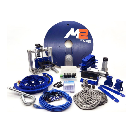
Automated cutting machine kit
Hide thumbs
Also See for M2:
- Complete beginner assembly manual (45 pages) ,
- Complete beginner assembly manual (38 pages) ,
- Setup manual (14 pages)

Related Manuals for MAKER MADE M2


Summary of Contents for MAKER MADE M2
- Page 1 SETTING UP YOUR M2 AUTOMATED CUTTING MACHINE KIT The official assembly guide by Last Updated 8.12.2020 v1.8...
- Page 2 **Disclaimer: Due to the prototyping nature of CNC development during a global pandemic, some pictures may vary from the M2 parts in your kit. Let us know how this guide can be improved for beginners. We love to hear from you!** This work is licensed under the creative commons Attribution NonCommercial-NoDerivatives 4.0 International license.
- Page 3 M2 ASSEMBLY GUIDE WHAT’S IN YOUR KIT Quantity Item DUE Case-bottom DUE Case-top v1.2 Control Board v1.2 DUE Control Shield Micro-USB connector- 10ft AC/DC Power Adapter (3 meter lead cable) w/ Sticker 120/240 Volt Power Cable (to adapter) X/Y Axis Motors (ETONM)
- Page 4 M2 ASSEMBLY GUIDE : WHAT’S IN YOUR KIT Quantity Item Bag A Cotter Pins to Secure chain to ring Chain Guide Chain Alignment Spacer Chain Spacer Nail Chain Nail Bag B Cable Tie M5 Quick Link Arduino Screws Bag C...
- Page 5 M2 ASSEMBLY GUIDE BUILDING YOUR FRAME This work is licensed under the creative commons Attribution NonCommercial-NoDerivatives 4.0 International license. Last Updated 8.12.2020 Version 1.8...
- Page 6 We recommend reading this entire section before beginning. 1. PURCHASE LIST The first step to starting your M2 CNC adventure is to build the frame that will hold your material and the M2 while it cuts. The M2 mounts for your frame are included, but you will need to purchase the following from a local hardware store: Top Beam: 2"X4"10'...
- Page 7 2. BUILDING THE FRAME The Frame has 2 main parts: The Top Beam that holds the motors (we recommend attaching it to a wall) and the Wasteboard on which you will clamp the material you want to the M2 to cut.
- Page 8 M2 ASSEMBLY GUIDE Step 3: Attach last two Stud Mounts STEP 3 Attach last 2 Stud Mounts to wall for Wasteboard Stud Mounts directly below first Stud Mounts ASSEMBLY GUIDE CONT. STEP 4 Attach Footer to Legs Step 4: Attach Footer to Legs...
- Page 9 Bag D M2 ASSEMBLY GUIDE STEP 5 Attach Wasteboard to Legs Step 5: Attach Wasteboard to Legs 6pcs long wood screws in Bag D Rest Wasteboard on Footer STEP 6 Attach Support Piece to backside of Wasteboard 4pcs long...
- Page 10 M2 ASSEMBLY GUIDE A (1:4) 2pcs #6 x 2 " Wood Screws 4pcs long STEP 7 wood screws Attach Motor Mounts in Bag D Motor Mounts Enlarged view of Motor Mount on beam Attach Motor Mounts on top edge of Top Beam,...
- Page 11 M2 ASSEMBLY GUIDE 3. MOUNT MOTORS The M2 moves side to side (X,Y) from the commands given to the motors by the Arduino DUE. The motors mount into the Motor Mounts on the ends of the Top Beam. Bag E...
- Page 12 M2 ASSEMBLY GUIDE 4. MOUNT ARDUINO DUE At the M2’s core is an Arduino DUE microcontroller. We recommend mounting the DUE to the wall behind your Wasteboard, but it can be mounted in any safe location where it won’t be stepped on or conflict with the M2 during operation.
- Page 13 M2 ASSEMBLY GUIDE STEP 2: Plug in MicroUSB into top port next to power (RX) (shown here without case) STEP 2b: If mounting without case, mount Control Shield to DUE board. Line up the pins as shown and be careful they don’t bend...
- Page 14 M2 ASSEMBLY GUIDE STEP 3: Attach left motor into far right port STEP 4: Attach right motor into far left port This work is licensed under the creative commons Attribution NonCommercial-NoDerivatives 4.0 International license. Last Updated 8.12.2020 Version 1.8...
- Page 15 M2 ASSEMBLY GUIDE STEP 5: Attach M2 control wire to remaining port STEP 6: Plug in power into top Control Shield (top power port). This work is licensed under the creative commons Attribution NonCommercial-NoDerivatives 4.0 International license. Last Updated 8.12.2020...
- Page 16 M2 ASSEMBLY GUIDE 6. PLACE WASTEBOARD AND MATERIAL Your Wasteboard will sit on the footer and be clamped (or screwed) to the Wasteboard Stud Mounts on the top. Always clamp or screw the material you’re cutting to the Wasteboard Stud Mounts so it doesn’t move.
- Page 17 M2 to the frame. **Due to the pitfalls of the global pandemic, the pictures in this section will unfortunately be different from your M2 kit. We’ll be posting an updated version as soon as we can and appreciate your understanding.
- Page 18 M2 ASSEMBLY GUIDE 1. FINISH Z AXIS ASSEMBLY In this photo is a fully assembled Z-axis assembly. Follow the instructions to complete on your own. STEP 1 Attach Z-Axis Motor Bracket, but don’t fully tighten (will tighten fully when belt is attached).
- Page 19 M2 ASSEMBLY GUIDE STEP 2 Attach Z Motor to bracket. Note which side of the slot the motor is on. Make sure to mount on the right side as shown. Button Head Screw M5-0.8x8mm Bag with Belt STEP 3 Attach gear to motor, ensure one grub screw is on flat side of motor shaft. Make sure to use 2 grub screws when mounting.
- Page 20 M2 ASSEMBLY GUIDE STEP 4 Attach Z axis gear on top of lead screw, ensure grub screw is tightened on flat side and gear is flush with top of screw and lined up with Z motor gear you just installed. Make sure to use 2 grub screws when mounting.
- Page 21 Tighten by gripping Z Axis Motor and pulling toward yourself until the belt is very tight. Use your other hand to tighten the Z-Axis Motor Bracket screws Important: Be sure that your belt is tight! If the belt is loose, your M2 will not move properly. This work is licensed under the creative commons Attribution NonCommercial-NoDerivatives 4.0 International license.
- Page 22 M2 ASSEMBLY GUIDE 2. MOUNTING SLED BRACKETS STEP 1 Build roller bearing carriage by placing one blue carriage mount on either side of ring. Insert shoulder bolt up through bottom of one carriage, slip one washer over bolt, then one ring bearing, then another washer.
- Page 23 M2 ASSEMBLY GUIDE STEP 3: Attach ring to sled through predrilled holes by placing ring on sled centered around router. Each L-bracket has six small holes, insert a small screw through each to tighten. Bag G: Wood Screws #6 x3/8”...
- Page 24 M2 ASSEMBLY GUIDE STEP 4: Place dust collection cover in center sled slot STEP 5: Attach router mount to Z-Axis Assembly with 4pcs of M5x8mm Button Head Screws Allen Wrench from Bag E This work is licensed under the creative commons Attribution NonCommercial-NoDerivatives 4.0 International license.
- Page 25 M2 ASSEMBLY GUIDE STEP 6: Attach Z-axis Assembly to sled using 6pcs M4 x 20mm Flathead Screws from Bag Z inserted through bottom, don’t tighten fully until router is centered Note: These bolts fasten with a T-nut. A T-nut works by being specially designed to turn sideways when being tightened.
- Page 26 M2 ASSEMBLY GUIDE 3. ATTACH AND CENTER YOUR ROUTER STEP 1: Attach bit to router, insert into router clamp, and tighten clamp. STEP 2: Center the router by moving the Z-Axis Assembly back and forth until bit is in center. Tighten T-nuts and ensure Assembly is tightly attached to the frame.
- Page 27 M2 ASSEMBLY GUIDE STEP 4: Plug in Z-Axis Motor by pulling cord from bottom of waste board to attach STEP 5: Attach PVC Dust Collection Elbow under Z-Axis motor This work is licensed under the creative commons Attribution NonCommercial-NoDerivatives 4.0 International license.
- Page 28 The chain can snap back causing damage to self and surroundings. The M2 moves in the X and Y position by the use of chains connected to the motors. The following instructions are to install the chains on a 4’x8’ frame.
- Page 29 M2 ASSEMBLY GUIDE STEP 3: Measure 31” (78cm) of one chain from nail toward center of Top Beam, place Motor Sprocket for Chain in loop, and attach Quick Link Bag A Bag B STEP 4: Attach spring and tighten quick link, with link nut facing away from beam This work is licensed under the creative commons Attribution NonCommercial-NoDerivatives 4.0 International license.
- Page 30 M2 ASSEMBLY GUIDE STEP 5: Measure 31” (78cm) of opposite chain, place sprocket, and attach quick link, do not tighten STEP 6: Stretch out spring and attach end to open quick link, tighten quick link Warning: Be careful when handling chains, they can snap back causing damage to self and surroundings.
- Page 31 When you have enough slack in the chain, thread through the opposite Carriage Mount and attach with a cotter pin. Let go of the sled and it should rest against plywood or MDF. Your M2 is ready to calibrate! Warning: Beware of chain tension! We recommend a friend help connect the spring and each person wear safety goggles during stretching.
-
Page 32: Calibration & Operation
GET A DIGITAL .SVG FILE 1. Digital file: You must have a digital file to CNC with the M2. We suggest a black and white SVG file. There are many files available online and tutorials on how to create them on YouTube! 2. - Page 33 3. Choose depth: Click on your file and “cut” tab in the dialog box to choose how deep the M2 will cut. If your SVG is split into multiple parts or isolatable, you can select different parts of your file to cut different depths.
- Page 34 M2 ASSEMBLY GUIDE 4. Material dimensions: You can change material dimensions by clicking the “material” tab. Select the material you are cutting and the size to save it in the Gcode. 5. Resize/move: Once your model is selected, you can also resize it by dragging the small gray boxes around your file.
- Page 35 Change the bit settings to the same bit that is on your router. Click the “bit” tab and select your bit. There are preset bits for the X-carve, but the best way to change it for the M2 is to scroll to the bottom of the tab and manually type in your bit size.
- Page 36 (0,0). You can arrange your file to start based on where you home your M2. Either select and move all the parts of your file or click the “shape” tab in the dialog box after selecting your model. Click the bubble in the five part matrix to choose where your M2 will start.
- Page 37 M2 ASSEMBLY GUIDE 9. File management: To keep track of the Gcode files you create to use them again, we suggest naming the file with the bit size and thickness of the material. Click “untitled” in the menu bar to change the name.
- Page 38 M2 ASSEMBLY GUIDE 10. Generate Gcode: To generate your Gcode to cut, click “Machine” > “Advanced” to bring up the Gcode menu. Then click “Generate g-code”. This work is licensed under the creative commons Attribution NonCommercial-NoDerivatives 4.0 International license. Last Updated 8.12.2020...
- Page 39 M2 ASSEMBLY GUIDE Then “Export g-code” to save the Gcode. You will upload this Gcode into the Machine Control Application. You can leave the other default setting alone until you become more comfortable with your M2. You finished exporting and are ready for the next stage! This work is licensed under the creative commons Attribution NonCommercial-NoDerivatives 4.0 International license.
- Page 40 *See Chapter 3: Assembling your M2 and be sure your motors are connected! ATTENTION: When connecting your M2 for the first time, be sure to be close to a power source to unplug if anything does not go as planned.
- Page 41 M2 ASSEMBLY GUIDE 4. SELECT PORT: Choose the USB port you plugged your M2 into. Makerverse will remember the port the next time you login. 5. CONNECT M2: Click “Open”. Leave “Connect automatically” selected for Makerverse to connect to your M2 automatically the next time you use it.
- Page 42 6. VERIFY CONNECTION AND ENTER Z-STEPS You will know your M2 is connected when you see the Grbl Gcode readout in the Console, shown below. If you don’t see lines of code, then your M2 is not connected. To disconnect at any time, click close.
- Page 43 M2 ASSEMBLY GUIDE 8. MACHINE SETTINGS - MEASURE DISTANCE BETWEEN MOTORS AND MOTOR OFFSET: Before the M2 will work properly, the distance between your motors and the distance from your Wasteboard must be entered into CNCjs. Measure from the 8 o’clock position on your left motor and the 4 o’clock position on your right motor.
- Page 44 M2 for future use. 9. MACHINE SETTINGS - MEASURE WORKSPACE Before the M2 will work properly, the workspace dimensions must be entered. Measure the size of your workspace and press enter. The standard 4x8’ values are default.
- Page 45 10. HOME TO (0,0): The home position must be set on your M2 before you can CNC or jog your motors. If your sled is not already in the center of your wasteboard, click the Set Home command and move the M2 sled and chains to the center of your wasteboard using the X-, X+, Y-, and Y+ jog commands on the right.
- Page 46 M2 ASSEMBLY GUIDE Once the M2 is moved to the center, click the blue “Set Home” button to set home. X, Y, and Z are now set to zero (0,0,0)on the M2 and will be remembered on the M2’s internal memory.
- Page 47 You’ll know your Gcode loaded correctly when CNCjs displays the paths of the Gcode you loaded! You already set the dimensions and depths in Easel for the M2, so it’s ready to start! We recommend a one foot or one meter square as your first test cut for calibration.
- Page 48 We recommend running the first cut with the router off to ensure everything is running properly. When your M2 is cutting for the first time, be close to the power source to stop all opperation if something goes awry. After your first test cut, you will measure and compare the real values to the values of your Gcode for scaling, described in step 16.
- Page 49 14. PAUSE/STOP To pause or stop the M2, click the “Pause” button on the top bar. Once the M2 is paused, you will be able to stop the project by clicking the “Stop” button next to it. It must be paused before you can stop the project! 15.
- Page 50 Then enter the Y values in the Y Scaling. Now when you run your M2, you can begin from where you set your temporary home position! We recommend cutting 3 or 4 times and measuring until your cuts are near exact to your Gcode.
- Page 51 M2 ASSEMBLY GUIDE TIPS & SAFET Y WARNINGS We recommend attaching a hook to the Top Beam to hold the M2 when not in operation. Click here to check out updates on our FAQ section! Always wear safety goggles. Always clamp the material you’re cutting to the Wasteboard Stud Mounts so it doesn’t move during operation.
- Page 52 M2 ASSEMBLY GUIDE CNCjs does not control your router, it only controls your M2. You must manually turn your router on and off. In case of an error always turn off your router before you turn off your M2. Always remember to turn on your router before clicking “Run” in CNCjs and turn off your router after the M2 is paused, stopped, or has completed the project.
Need help?
Do you have a question about the M2 and is the answer not in the manual?
Questions and answers