Table of Contents
Advertisement
Quick Links
The Sensor Input Kit receives sensor data from status, flow, temperature, rain buckets, and
pressure sensors, then relays that data to the Lynx computer. There, it can be used to monitor
conditions and automatically respond to user-defined alarms.
•
Sensor data is stored in the VP satellite for 12 hours and transmitted back to Lynx
every 2 hours.
•
Current sensor information and alarm status can be viewed in the VP faceplate.
•
Central-based or stand-alone alarm responses can be configured for any sensor input.
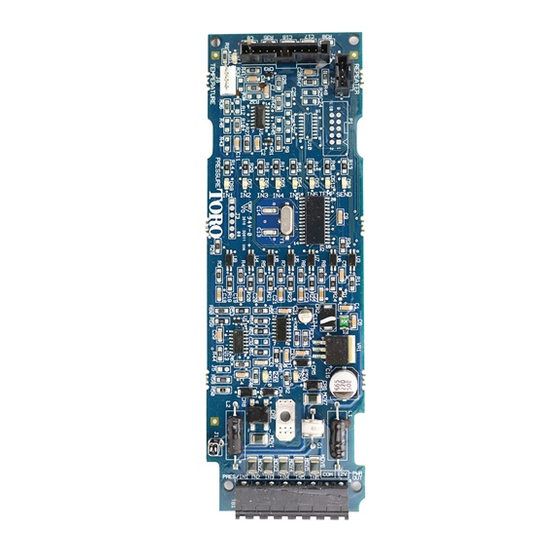
Sensor Input Board Overview
5V LED
Indicates 5V is active.
Temperature Probe Connector
Connector for temperature
sensor probe.
IN1 LED - Pressure
Indicates if a pressure sensor
is present.
IN2-IN6 LEDs
Indicate sensor activity for
channels IN2-IN6.
24V LED
Indicates 24V is active.
24V Connections
Connection to receive 24V
AC from satellite.
Terminals
Network VP Sensor Input Kit (SIK)
Installation Instructions
Kit Components
• Sensor Input Board
• Surge Board
• Mounting hardware
• Fuse
• Cables
Power Distribution Connector
Receives 5V and 9V to
power the Sensor Input
Board.
Temperature LED
Indicates if a temperature
sensor is present.
Transmit LED
Indicates data packet
is being sent.
12V LED
Indicates 12V is active.
Terminal
Description
IN 1
Pressure Sensor Input
IN 2
Flow, Rain, or Status Sensor Input
IN 3
Flow, Rain, or Status Sensor Input
IN 4
Flow, Rain, or Status Sensor Input
IN 5
Flow, Rain, or Status Sensor Input
IN 6
Flow, Rain, or Status Sensor Input
COM
12 V Ground or Common
12V
12 V DC Output
1
Advertisement
Table of Contents

Related Manuals for Toro SIK


Summary of Contents for Toro SIK
- Page 1 Network VP Sensor Input Kit (SIK) Installation Instructions The Sensor Input Kit receives sensor data from status, flow, temperature, rain buckets, and Kit Components pressure sensors, then relays that data to the Lynx computer. There, it can be used to monitor •...
- Page 2 Sensor Input Board Installation 1. Remove the front panel door and power Figure 1 down the satellite controller. 2. Locate an available output board slot to install the sensor input board. If the satellite is utilizing all output board slots, remove the last station output board and use that location.
-
Page 3: Sensor Installation
Pressure Sensor wrapped sheild, PVC Toro sells a pressure sensor kit (part number PRESS200- jacket. SEN-KIT), composed of a 6’ long sensor cable and a pressure sensor. Steps 1. At the sensor terminal board, secure the pressure sensor’s black lead to screw IN 1 and white lead to... - Page 4 Temperature Probe Connection port. See Sensor Input Board Overview on page 1 for port location. The Toro temperature sensor will be available in late 2017. Sensor Configuration - Local Mode Sensor configuration can either be done at the satellite in Local Mode or at a Central computer running Lynx.
- Page 5 • Start Station. Starts a specified station. Flow Sensor Configuration • Cancel Station. Cancels a specified station. Input : 2 Typ:FLOW Cancel All. Cancels all irrigation activity. • I_WTW : 06:00pm Rain Hold. Places a rain hold on the controller for a •...
- Page 6 correct K Value. Status Sensor Configuration Off_s: Review your flow sensor’s documentation for its Input : 4 Typ:STAT correct Offset value. : Norm Close Alarm : On PPG (if Bermad selected): Pulse per gallon based on flow QTime : 10s meter wiring.
-
Page 7: Clearing Alarms
Lynx Smart Satellite Sensor Kit. Check your satellite’s firmware: 1. Press the Diagnostic button. 2. Turn the Command dial to Revision. 3. Check Revision number. If firmware revision is less than 2.0, see your Toro distributor for a firmware update. -
Page 8: Configuring Sensors
Sensor Configuration - Lynx ® Sensor configuration can either be done at the satellite in Local Mode or at a Central computer running Lynx. If communication is established between a satellite and a Lynx system, the Lynx system will overwrite all locally defined sensor configuration information. Meaning, if operating a Lynx system, the sensors must be configured with Lynx. - Page 9 Reviewing Sensor Data Figure 4 It is possible to review sensor information in realtime or historically. Realtime: Click Utilities then Sensor Dashboard. Select the Sensor Input Board to monitor. You will see a screen similar to Figure 4, though the number and type of sensors might be different, as well as the ranges for the sensors.
-
Page 10: Electromagnetic Compatibility
Neither Toro nor Toro Warranty Company is liable for indirect, All implied warranties, including those if merchantability and incidental or consequential damages in connection with the use fitness for use, are limited to the duration of this express warranty.
Need help?
Do you have a question about the SIK and is the answer not in the manual?
Questions and answers