
Related Manuals for ALTER SM1280 Series

Summary of Contents for ALTER SM1280 Series
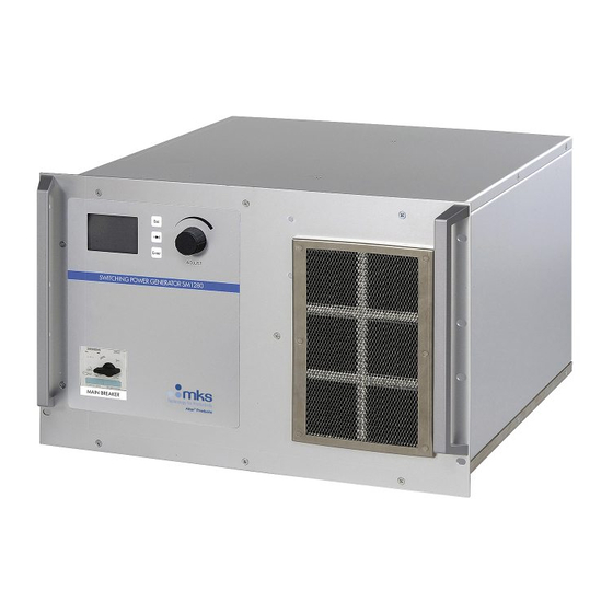
- Page 1 SM 1280 SM1280D for line 3 x 208V SM1280T for line 3 x 400V SM1280U for line 3 x 480V SWITCHING POWER GENERATOR WITH EMBEDDED MICROCONTROLLER FOR 6 KW MAGNETRON TECHNICAL NOTE (issue May 2009)
-
Page 2: Ce Declaration
SM 1280 CE Declaration of Conformity Dichiarazione di Conformità CE Manufacturer’s Name: ALTER s.r.l Nome del Costruttore: Manufacturer’s Address: Via Curie, 8 - 42100 Reggio Emilia - Italy Indirizzo del Costruttore: Declare that the microwave generator: Dichiara che il Prodotto:... -
Page 3: Rohs Conformity
Decreto Legislativo D.L. n. 151 – 25/07/2005 (WEEE and RoHS) Starting from September 2005 Alter has set the rule to accept only RoHS compliant components from its Suppliers. At the present date the 99% of components in our stock is RoHS compliant. -
Page 4: Table Of Contents
SM 1280 General Informations Contents Alarm troubleshooting 28, 29 This equipment satisfy the European Standard EN 61010- 1 (=CEI 66-5) (=IEC 1010-1) approved by CENELEC on 9/3/1993. Bit alarm table 6 BUS operation 13 With reference to EN 61010-1 standard, note: this appliance must be installed and serviced only by qualified CE Declaration 1 personnel. -
Page 5: General Description
SM 1280 Handling Warnings i.e. in a standard cabinet with an height of 2 meters, arranged to receive 19” racks, up to 5 SM1280x units may be easily installed. The SM1280x has two handles on the front panel to help The user must provide a proper cooling flow: the cooling air unpacking and handling operations: never use only the enter into the unit from the front side, it passes through the... - Page 6 SM 1280 Description of versions 0 - 1 - 50 -51 The front panel includes 5 status LEDs: The rear panel comprises the following (see drawings): POWER ON (GREEN): ON when power is present 1) 7 pins socket for main supply (CONN #1) [male] 2) 14 pins socket for mw head signals (CONN #4) [female] INTERLOCK ON (WHITE): ON when Interlock chain...
-
Page 7: Bit Alarm Table
SM 1280 Description of version 2 Monitor 2 output signal: 0÷10 V, 1V= 200 mA for anode current Note: Monitors outputs are designed for a receiver impedance The front panel of the “Display version” (vers. 2) includes a of at least 30 kOhm (to guarantee a maximum error of 1%) graphic display and manual commands. -
Page 8: Cleaning
SM 1280 Environmental conditions Fuse F1 specs on M416 board: - Size, type: 5x20 mm - Speed action: slow (T) Use: Indoor use only - Rated current: Altitude: tested up to 2,000 m - Rated voltage: 250 V Temperature: 5°C to 40°C (41°F÷104°F) @ 200 m /h cooling flow Equipment maintenance... -
Page 9: Equipment Installation
1. use a standard 19” wide enclosure with a depth of 800 mm ALTER may supply the HV cable with lenght on request. (32”); VI) The connector #3 provides the power supply for the 2. -
Page 10: Power-Up Procedure Vers. 0 - 2 - 50
SM 1280 disconnecting device for the SM1280. : it’s a waiting state, the unit is powered but not ready STAND XIV) The connector #1 must never be used as a switch-off as the magnetron filament is not powered; all the working device. -
Page 11: Manual Commands
SM 1280 Working Modes Software Menu Description (vers 2 only) It’s the default page at Power The version 2 has a graphic display, some manual commands ON. This view reports the sof- on the panel and may be driven manually, as well as by tware version and lasts only few external commands (PLC) and thru the RS 232 port using the seconds. -
Page 12: Firmware Upgrade
SM 1280 rate any output power, when >1Vdc the unit generates power This is the set-mode submenu: it proportional to this signal value. allows to select Manual or Exter- The CPU drives the unit to obtain an electrical output power nal Control. -
Page 13: Internal Settings
SM 1280 interlock relay from the CPU in case of alarm. If it is ON, only During the bootloader wait time, the red ALARM led is on: if the opening of the MICRO CARTER switch can de-energize no code is sent, then the previous code is executed, and it is not the interlock relay, cutting in this way the head supply and possible to change it without switching the unit off. -
Page 14: Bus Operation
SM 1280 Equipment operation with versions having network capability (vers 1 -51) ATTENZIONE! RS 232 LA MANUTENZIONE DEVE ESSERE Power-up procedure CONN #5 FATTA DA PERSONALE QUALIFICATO. RISCHIO DI SCARICHE ELETTRICHE BUS ADDRESS ALL’INTERNO! CONN #6 WARNING! Before powering-up the equipment, double check to have REFER SERVICE TO QUALIFIED PERSONNEL ONLY. -
Page 15: Conn. Rs232 Wiring
SM 1280 entered a “Process Active” state after the first command, Module Status LED: A test sequence is performed on this if the MASTER stops to run (for any reason), the SM1280 LED during startup power supply does not detect any abnormal situation and keep LED State Description running the output in the state they were. -
Page 16: Conn.# 1 Wiring Vers. 0 - 1 - 2
SM 1280 Connector # 1 wiring (vers. 0 - 1 - 2) page 15 of 30 File: SM1280_r1eng - May 2009 - Technical note: SM 1280... -
Page 17: Conn.# 1 Wiring Vers. 50 - 51
SM 1280 Connector # 1 wiring (vers. 50 - 51) page 16 of 30 File: SM1280_r1eng - May 2009 - Technical note: SM1280... -
Page 18: Conn.# 3, 4, 5 Wiring
SM 1280 Connector # 3,4,5 wiring page 17 of 30 File: SM1280_r1eng - May 2009 - Technical note: SM 1280... -
Page 19: Conn.# 6 Wiring
SM 1280 Connector # 6 wiring SM1280X OPTO-INSULATED CONTROL INTERFACE CONN.#6 (D-SUB 25 PIN F) MONITOR SIGNALS Magnetron voltage and CONN. #6 current Monitor valid for all versions Output Voltage V Pin #2 On the “D” type fermale connector #6, installed on the rear panel = 1000 V (return on pin #15) of the PSU, there are two monitor signals, in the range 0 - 10Vdc... -
Page 20: Components Layout
SM 1280 COMPONENT LAYOUT page 19 of 30 File: SM1280_r1eng - May 2009 - Technical note: SM 1280... -
Page 21: Components List
SM 1280 Component list (See drawing pag.19) SM1280 T/U Model D Model Pos. Q.ty Description Note CPU board M416 800000416/1280 Driver board M311 800000311/1280T Power board M408 800000408 Fan, 230V VE2GRE120/6221R Fan capacitor 2µF CR202A450 LCD board M292 800000292/AC440 LED board M417 800000417.0 Magn. - Page 22 SM 1280 SM1280 T/U Model D Model Pos. Q.ty Description Note 7 pins Socket AMP/CPC MOCPC07/2113981 CONN#3 female pin AMP type III MOCPCX/1630881 CONN#3 pins 7 pins Plug AMP/CPC (*) PLUG#3 (**) male pin AMP type III (*) PLUG#3 pins (**) 7 pins Socket AMP/CPC MOCPC07/2061371...
- Page 23 SM 1280 Internal Wiring schematic (1 of 6) SEZIONE DI POTENZA / POWER SECTION VERSIONI / VERSIONS SM1280T/yyy0, SM1280T/yyy1xxx, SM1280T/yyy2 3RV1331-4DC10 SIEMENS FL50FCD10 CORCOM CONN.#1 TOR1 TOROIDE HS72T40 Int. autom. 25A GND IN GND OUT SKD6212 GROUND BAR GROUND SCREW MAIN LINE INPUT 3x400V GRIGIO/GREY...
- Page 24 SM 1280 Internal Wiring schematic (2 of 6) MAIN LINE INPUT SEZIONE DI POTENZA VERSIONI / POWER SECTION VERSIONS 3 x 400V + SM1280T/yyy50, SM1280T/yyy51xxx, SM1280T/yyy52 EARTH 3RV1331-4DC10 SIEMENS FL50FCD10 CORCOM CONN.#1 TOROIDE HS72T40 TOR1 Int. autom. 25A GND IN GND OUT SKD6212 GROUND BAR...
- Page 25 SM 1280 Internal Wiring schematic (3 of 6) SEZIONE DI AT - POTENZA ALLA TESTA/ HV SECTION - HEAD POWER TUTTE LE VERSIONI / ALL VERSIONS CONN.#3 NEUTRO FASE FASE FIL BLU/BLUE FASE LAMPADA GRIGIO/GREY MARRONE/BROWN NERO/BLACK GROUND BAR IND 42FI1690A/AT CAVO AT/ CONN.#5 HV CABLE...
- Page 26 SM 1280 Internal Wiring schematic (4 of 6) SEZIONE ALLARMI TESTA - CONTROLLO / HEAD ALARMS - CONTROL SECTION INGRESSO ALLARMI E SEGNALI DALLA TESTA/ HEAD ALARMS AND SIGNALS INPUT CONN.#4 ARC DETECTOR TERM.MAGNETRON AIR PRESSURE H2O FLOW MICROSWITCH ON HEAD COVER BIAS MICROSWITCH ON HEAD COVER HEAD ENABLE1 GND HEAD...
-
Page 27: Internal Wiring Schematic
SM 1280 Internal Wiring schematic (5 of 6) SEZIONE COLLEGAMENTI INTERNI/ INTERNAL CABLING SECTION ROSSO/RED MODULO /MODULE BLU/BLUE SEMIKRON VERDE/GREEN ARANCIO/ORANGE OCCHIELLO 6mm NERO/BLACK AMP Modu 10 Vol ROSSO/RED MODULO/MODULE BLU/BLUE SEMIKRON VERDE/GREEN ARANCIO/ORANGE OCCHIELLO 6mm NERO/BLACK AMP Modu 10 Vol 80∞... - Page 28 SM 1280 Internal Wiring schematic (6 of 6) SEZIONE CPU2/ CPU2 SECTION SOLO VERSIONI ONLY VERSIONS SM1280T/yyy2 SM1280T/yyy52 Phoenix 3.81 6P Vol Phoenix 3.81 6P Vol +12V -12V M292 NB: non M416_SM1280T CPU2 standard BOARD FLAT4 Flat Cable 80 Pin page 27 of 30 File: SM1280_r1eng - May 2009 - Technical note: SM 1280...
-
Page 29: Alarm Troubleshooting
SM 1280 ALARM TROUBLESHOOTING As soon as an alarm is generated, the microwave output is switched off, but the alarm condition is latched, and can be immediately stopped, the alarm relay contact opened, the reset only removing the hardware ENABLE input for at least alarm code relay contacts set to the appropriate values, and the 2 seconds. - Page 30 SM 1280 ALARM TROUBLESHOOTING Code Description Cause/Solution Low Air If it isn’t used the related input must be grounded. Pressure If used, contact grounded=OK, open=alarm Check head air filter. from head If it isn’t used the related input must be grounded. Low Water Flow If used, contact grounded=OK, open=alarm from head...
-
Page 31: How To Order
SM1280T.ALT51CAN: input 400V, version with separate input for auxiliary voltage, with CAN bus interface Alter reserves the right to improve or modify this products, at any time, without obligation to notify any person or entity of such changes. No part of this publication may be reproduced without the express written consent of Alter.
Need help?
Do you have a question about the SM1280 Series and is the answer not in the manual?
Questions and answers