Table of Contents
Advertisement
Techno CNC Systems, LLC. ©2015 (06/17)
WinCNC
Titan Series WinCNC Manual
This document will provide a quick guide to the set up and operating
procedure of the Techno Titan CNC Router with a WinCNC Controller.
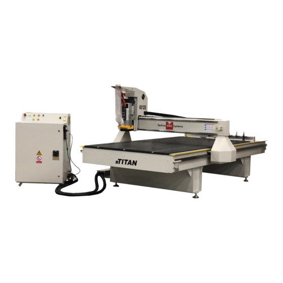
The Techno Titan CNC Router is powered by high precision stepper motors
and controlled by a PC with a WinCNC Control System.
1
Call: 1-631-648-7481 or Visit: support.technocnc.com
Advertisement
Table of Contents

Related Manuals for Techno CNC Systems Titan Series


Summary of Contents for Techno CNC Systems Titan Series
- Page 1 Techno CNC Systems, LLC. ©2015 (06/17) WinCNC Titan Series WinCNC Manual This document will provide a quick guide to the set up and operating procedure of the Techno Titan CNC Router with a WinCNC Controller. The Techno Titan CNC Router is powered by high precision stepper motors and controlled by a PC with a WinCNC Control System.
-
Page 2: Table Of Contents
TABLE OF CONTENTS Forklift Guide .................Page 3 Safety Instructions ...............Page 4 Colleting Guidelines ...............Page 5 Initial Setup 1.1 Titan Series Series Installation .........Page 6 1.2 Titan Series Series Installation .........Page 10 Controller Functionality 2.1 Control Panel Functions .............Page 12 2.2 Enabling the Machine ...........Page 13... -
Page 3: Forklift Guide
WinCNC Titan Series WinCNC Manual Call: 1-631-648-7481 or Visit: support.technocnc.com... -
Page 4: Safety Instructions
WinCNC Titan Series WinCNC Manual Safety Instructions READ THESE INSTRUCTIONS THOROUGHLY BEFORE OPERATING MACHINE. DO NOT OPERATE MACHINE IF YOU ARE UNFAMILIAR WITH THESE SAFE OPERATING INSTRUCTIONS. DO NOT OPERATE MACHINE WITHOUT KNOWING WHERE THE EMERGENCY STOP SWITCH IS LOCATED. - Page 5 WinCNC Titan Series WinCNC Manual WARNING! THE SPINDLE WILL BE DAMAGED IF UNBALANCED EQUIPMENT IS USED. AIR SUPPLY MUST BE FILTERED AND DRY. Call: 1-631-648-7481 or Visit: support.technocnc.com...
-
Page 6: Initial Setup
Titan Series WinCNC Manual I. Initial Setup 1.1 Techno Titan Series Installation Carefully remove the Titan from its wood pallet. Be sure to remove the bolts from its four leveling feet insertion holes, as well as anything stowed under the Titan during shipping. - Page 7 WinCNC Titan Series WinCNC Manual The Electronics are housed in the large NEMA enclosure as shown in Fig. 1..2a. When unpacking the machine avoid twisting the cable carrier that guides the cables to the motors. Enclosure A- Controller Board. Fig. 1.2a B- 24Volt PSU.
- Page 8 WinCNC Titan Series WinCNC Manual Unpack the PC, monitor, keyboard and mouse and began mounting the equipment. Attach the monitor to the provided mount, place the PC in the side tray and connect both to a 110VAC power source. Rout keyboard and mouse to PC and make sure the monitor is also connected.
- Page 9 WinCNC Titan Series WinCNC Manual Call: 1-631-648-7481 or Visit: support.technocnc.com...
-
Page 10: Titan Series Series Installation
WinCNC Titan Series WinCNC Manual 1.2 Vacuum Pump Installation Call: 1-631-648-7481 or Visit: support.technocnc.com... - Page 11 WinCNC Titan Series WinCNC Manual Call: 1-631-648-7481 or Visit: support.technocnc.com...
-
Page 12: Controller Functionality
WinCNC Titan Series WinCNC Manual II. Control Functionality 2.1 Control Panel Functions Power Emergency Gate Disable Stop Valve(s) Vacuum Control(s) Power Spindle Inverter Enable Port Readout Emergency Stop - This button will cut power to the entire machine. Used in emergency situation to completely stop the machine. -
Page 13: Enabling The Machine
WinCNC Titan Series WinCNC Manual 2.2 Enabling The Machine Once the electrical connections have been made, controller is powered by turning the main power switch, on the front of the machine, to the ON position (as shown in Fig. 2.2a). - Page 14 WinCNC Titan Series WinCNC Manual Once the machine has been powered up and adequate air pressure has been applied, the PC and monitor may be turned on and booted up. When the PC finishes loading, the Techno CNC Interface may now be lauched. Run the program by double clicking the Techno CNC Interface icon on your Windows desktop. Techno CNC Interface Call: 1-631-648-7481 or Visit: support.technocnc.com...
-
Page 15: Software Overview
WinCNC Titan Series WinCNC Manual 2.3 Techno CNC Software Controller: Overview The Techno CNC Controller has advanced features to provide the smoothest possible cuts. G-Code input is constantly buffered to ‘vector match’ moves. This means your machine only slows down when it needs to and then only as much as needed to stay within the acceleration parameters programmed. - Page 16 The following section contains a sample of the WinCNC software WinCNC display. Common components are labeled to provide clarity. Titan Series WinCNC Manual NOTE : This screen may differ from your screen layout, as it is highly customizable and may have been altered by the CNC ma- Program Operation: Overview chine manufacturer.
- Page 17 WinCNC Titan Series WinCNC Manual Tool Bar The tool bar is a collection of shortcut buttons that perform specific actions. START SOFT LIMITS Execute Enables/Disables command soft limit features line or job RESTART / SKIP VIEW Restarts a job at a Displays the current given line number job in the viewer VIEW HISTORY...
- Page 18 WinCNC Titan Series WinCNC Manual Viewer WinCNC contains a built in viewer window that will allow you to display the output of G-Code files before the job is actually run. By default, the viewer can also display a G-Code file line by line as it is run. G0 rapid moves are shown as a black dashed line. G1 feedrate moves are displayed as a solid blue line. To view a file before you run it, open the file in the command line and then press the viewer button on the toolbar. Once the object is loaded into the viewer the following controls can be used: Zoom In - click the left mouse button.
- Page 19 WinCNC Titan Series WinCNC Manual Function Buttons These buttons perform preset functions. They are used as shortcuts for many G-code operations. Go XY0 Home All Raises Z to its high limit Finds the machine’s limit and sends the machine switches. Should be to XY=0 performed at start-up.
- Page 20 WinCNC Titan Series WinCNC Manual WinCNC Controller Program Operation File Menu Open (CTRL+O) - Opens a file. Edit (CTRL+E) - Opens the editor. If a filename is in the command line, the editor opens that file. Simulate (CTRL+S) - Simulates a file running to check for errors and estimate run time.
- Page 21 WinCNC Titan Series WinCNC Manual WinCNC Controller Program Operation Digitize => Laser => Run Scan - Opens the laser digitization dialog box to set up laser scanning parameters. Digitize => Laser => Reprocess Data - Opens a data file from a previous laser scan used to re-generate a 3D object with different filtering options to improve the quality of the 3D object.
- Page 22 WinCNC Titan Series WinCNC Manual WinCNC Controller Program Operation Toolbars - Enable/Disable the main toolbar. Toolbars=> Size - Change toolbar from small to large. Refresh View (F5) - Refreshes the screen. Clear Screen (CTRL+C) - Clears the message display window.
- Page 23 WinCNC Titan Series WinCNC Manual WinCNC Controller Program Operation Jog Menu 0.001 (F6) - Sets jog increment to 0.001 units of measure. 0.01 (F7) - Sets the jog increment to 0.01 units of measure. 0.1 (F8) - Sets the jog increment to 0.1 units of measure.
- Page 24 WinCNC Titan Series WinCNC Manual WinCNC Controller Program Operation Start Motion - This button will begin the command or job listed in the command line. Restart - Allows you to pick a job file and the line to start that file on.
- Page 25 WinCNC Titan Series WinCNC Manual WinCNC Controller Program Operation Add a Rapid Move - Adds a rapid move to the manual digitized file. Add a Feed Move - Adds a feed move to the manual digitized file. Add an Arc Point - Used to add arcs into a manual digitized file.
-
Page 26: Program Shortcuts
WinCNC Titan Series WinCNC Manual 2.4 Program Shortcuts WinCNC Controller Program Operation Shortcut Keys File Menu Shortcuts Open Enter (with blank command line), CTRL+O Edit CTRL+E Simulate CTRL+S View CTRL+V Create Home File CTRL+H View Menu Shortcuts Refresh View Clear Messages... - Page 27 WinCNC Titan Series WinCNC Manual WinCNC Controller Program Operation Shortcut Keys continued Tool Bar Shortcuts Aborts the current file or command SPACE Pauses a file or command ENTER Starts/restarts a file or command Opens the command history box CTRL+R Opens the restart file box...
-
Page 28: Machine Startup - Homing 3.2 - Manaul Operation
WinCNC Titan Series WinCNC Manual III. Operating Tutorials 3.1- Machine Startup - Homing When starting the machine and WinCNC software, the first thing the operator should do is “Home” the machine. This allows the operator to check the functionality of the limit switches, and reference the machine so that previous origin positions can be used. Press “Home All” to home the machine. 3.2- Manual Operation The WinCNC controller supports two types of manual movement; Transit and Jog Increment modes. -
Page 29: Axis Window
WinCNC Titan Series WinCNC Manual 3.3- Axis Window The axis window is the primary display for current information about each axis on your machine. The current positions and velocities for each axis are displayed in the text boxes. Displayed above the position... -
Page 30: Functions
WinCNC Titan Series WinCNC Manual 3.5- Functions Main Function Windows This frame contains the fundamental operations for the CNC machine. These buttons are discussed in detail throughout the manual. Operator Panel This frame contains the “Start”, “Pause” and “Abort” controls. Start - Executes the loaded the G-code file Pause - Pauses a currently running G-code file. Press “Pause” again to continue Abort - Stops/Cancels any machine movement. This includes... - Page 31 Transit/Jog Buttons These buttons are what allow you WinCNC to initiate a manual transit or jog Titan Series WinCNC Manual movement from the console of the Tool Change computer that runs the machine. This frame houses the tool change controls. The In transit mode, holding the button operator clicks on the Tool he/she would like to pickup.
-
Page 32: Adjusting The Xyz Position/Wcs/User Origin
WinCNC Titan Series WinCNC Manual 3.6- Adjusting the XYZ Zero position/WCS/User Origin. XYZ zero position, Working Coordinate System (WCS), and User Origin are all the same thing. Different CAM systems and users just name the concept differently. For convenience XYZ zero position will be used in the rest of this manual. - Page 33 WinCNC Titan Series WinCNC Manual Setting the Z-axis Zero Position for Router usage. The Z-axis zero position can be set in two ways: Manually- Use the Z-axis directional arrows to move the tip of the router bit to the location of your Z=0 position as indicated by your G-code program.
-
Page 34: Running A G-Code File
WinCNC Titan Series WinCNC Manual 3.7- Running a G-code File Once the XY and Z zero positions have be set, the machine is now ready to execute a G-code program. Make sure your material is properly secured, the correct bit is inside the spindle and that the operator has the proper safety equipment on. -
Page 35: Advanced Tutorials
WinCNC Titan Series WinCNC Manual IV. Advanced Tutorials 4.1 Tool Changers About Using The Automatic Tool Changer When using the Automatic Tool changer, the operator may choose to drop off one tool and pick up another tool. This is useful for learning tool lengths, setting origins, and optimizing job files. Performing a Tool Change is a simple procedure, but one that must be done cautiously. - Page 36 WinCNC Titan Series WinCNC Manual Notes about Tool Changing The tool change process has many checks to ensure that the machine will perform properly and not cause damage to itself, the tools, or the operator. These checks include: Air Pressure (90-120 psi)
- Page 37 WinCNC Titan Series WinCNC Manual 4.2 Measuring Tool Lengths To measure the length of a tool for use in the automatic tool changer, the operator must first be sure that “Table Zero” is set. After the “Table Zero” is set, the operator can change to the tool that needs to be measured. Once the operator has the correct tool, the operator can click “Measure Tool” This will start the automatic tool measuring cycle. The machine will raise up, move to the fixed tool probe and slowly lower down until it touches the pad. Once it touches the pad, it will raise up, signifiying the tool has been learned. WARNING: Spoilboard cutter or any other cutter with dome bottoms cannot be set using the touch pad.
-
Page 38: Learning Pocket Positions
WinCNC Titan Series WinCNC Manual 4.3 Learning Tool Pocket Positions The Titan machine will already know the exact locations of the 8 tool holder pocket positions. However, it is possible that the operator may need to “relearn” these positions. This may happen if the machine goes out of square, if the pocket moves, or if the operator chooses to add an additional pocket to the rack. The process is as follows: Using the jog keys, the operator will move the machine very close to the tool stand rack. - Page 39 WinCNC Titan Series WinCNC Manual Saving Tool Pocket Positions Once the machine is in the pocket position and the operator has opened the “Tool Positions” menu, and the pocket positions can be learned. First, select the proper tool number from the position list. Then choose “Get Position” This will save the machines current position as the XYZ cooridinates for the selected tool.
-
Page 40: 4Th Axis
WinCNC Titan Series WinCNC Manual 4.4 Using the 4th Axis Rotary Setup Some Titan machines are equipped with a 4th axis rotary tables. These machines have true 4 axes control for CNC operations. On these machines, the rotary axis is referred to as the “B” axis. Its axis of rotation is parallel to the Y axis. The axis can be controlled through the “B- Clockwise” and B-Counter-Clockwise” buttons. These buttons will allow the operator to rotate the B axis so that the B-axis origin can be set. -
Page 41: Controller Commands (G, M And L Codes)
WinCNC Titan Series WinCNC Manual V. Controller Commands WinCNC Controller Command Reference Command Reference Parameters in [Brackets] are optional. XYZWIJ . . . Axis Specification X# Y# Z# Axis values are specified with a decimal point. A value with no decimal is read as an integer value. - Page 42 WinCNC Titan Series WinCNC Manual WinCNC Controller Command Reference Braces Used to substitute axis or parameter values in a line of G-Code. Internally defined variables as well as constant numbers can be used within the braces. Following is a list of internally defined variables and what they represent.
- Page 43 WinCNC Titan Series WinCNC Manual WinCNC Controller Command Reference Internally Defined Variables continued 1 if THC Manual Voltage Mode is enabled, 0 if disabled. 1 if THC Auto Voltage Mode is enabled, 0 if disabled. The specified output channel used to turn the torch on/off for THC.
- Page 44 WinCNC Titan Series WinCNC Manual WinCNC Controller Command Reference G Codes Rapid Move - G0 X# Y# Z# W# Moves to the position specified at Rapid velocity. G0 is modal. Af- ter a G0 is executed lines with no G-Code command are executed as a G0.
- Page 45 WinCNC Titan Series WinCNC Manual WinCNC Controller Command Reference Dwell - G4 X# Stops movement for the time specified by the X value in seconds. There is no limit to delay time. If no time is specified, then the machine will be stopped until the operator pushes ENTER. Place a comment after the dwell to prompt the operator.
- Page 46 WinCNC Titan Series WinCNC Manual WinCNC Controller Command Reference Cutter Compensation Off Turns off cutter compensation. Cutter Compensation Left - G41 O# Compensates for differences in nominal and actual tool diameters. Starts to the left on the first move. O# is the compensation amount on machines without a tool changer.
- Page 47 WinCNC Titan Series WinCNC Manual WinCNC Controller Command Reference Rapid Move - G53 X# Y# Z# W# Moves to the position specified at rapid velocity, ignoring tool mea- sures and local coordinates. G53 alone will lift all vertical or type 3 axes.
- Page 48 WinCNC Titan Series WinCNC Manual WinCNC Controller Command Reference Drill Cycle - G81 X# Y# Z# R# F# Moves to XY specified at Rapid velocity. Moves to R (clearing height) at Rapid velocity. Moves to Z specified at Feed velocity.
- Page 49 WinCNC Titan Series WinCNC Manual WinCNC Controller Command Reference Absolute Mode Can be specified with other G-Codes on any line. XYZW values from the current line forward are read as absolute coordinates. IJ values are always relative to the current XY position, not absolute positions regardless of G90/G91 mode.
- Page 50 WinCNC Titan Series WinCNC Manual WinCNC Controller Command Reference G92.2 Shift LZ Coordinates - G92.2 X# Y# Z# W# Similar to G92.1 except that the coordinate system shift is added to the current local coordinates instead of replacing them. This is useful for ‘jogging’...
- Page 51 WinCNC Titan Series WinCNC Manual WinCNC Controller Command Reference L Codes Save Positions - L1 N# V# Store values is the saved positions file. Can store a value in one of the 30 existing ‘H’ registers. N# is the desired ‘H’ register number, can be 0 to 29.
- Page 52 WinCNC Titan Series WinCNC Manual WinCNC Controller Command Reference Turns Backlash Compensation On, Restore INI values for all axes. Examples: L8XY - Turn Backlash Compensation On, Restore INI values for specified axes. L8X.001 - Turns Backlash Compensation On, Set new value for specified axis.
- Page 53 WinCNC Titan Series WinCNC Manual WinCNC Controller Command Reference Set Axis Mapping - L11 XYZW Allows re-mapping of axis inputs. Specify the axes that should receive the input from XYZW in that order. Specify L11 alone to return to normal parsing.
- Page 54 WinCNC Titan Series WinCNC Manual WinCNC Controller Command Reference Enable Soft Limits - L20 [X1, X2] Enable Soft Limit and Boundary Checking: L20 X1 enables Bound- aries only. L20 X2 enables Soft Limits only. L20 alone enables both. Disable Soft Limits...
- Page 55 WinCNC Titan Series WinCNC Manual WinCNC Controller Command Reference Clear Home Flags - L29 XYZ Clears all require home flags. Axes can be used with the com- mand to clear require home flags only on the specified axes. L29.1 Ignore Home Flags Ignores require home flags for all axes during execution of the cur- rently running file.
- Page 56 WinCNC Titan Series WinCNC Manual WinCNC Controller Command Reference AutoAuxOut Disable - L35 D# Disables the auxiliary output that is turned on by the L34 com- mand. L35 D# sets the dwell time in seconds when the channel is set to off. When the ‘D’ parameter is used with the L35 command the “AutoAuxOut”...
- Page 57 WinCNC Titan Series WinCNC Manual WinCNC Controller Command Reference Pump Velocity Mode On Enables velocity matched pump control. Pump Purge Mode On Sets pump to purge mode. Pump Off Stops the pump. Pump Off with Auto Reverse Stops the pump, using auto reverse.
- Page 58 WinCNC Titan Series WinCNC Manual WinCNC Controller Command Reference L82.3 Calibrate Digitizing Probe Calibrates, or stores, the distance from the probe contact point to the table surface. Measures Z Depth - L83 X# Y# L83 command will do a one-shot Z probe at the specified location, and record the XYZ position values in a comma delimited text file named SCAN.CSV.
- Page 59 WinCNC Titan Series WinCNC Manual WinCNC Controller Command Reference L112 Test Tool Number - L112 T#. Skip next line if tool number is equal to T#. L113 Spindle Speed Conditions - L113 L# H# V# Skip the next line if the V# is not greater than the L# and less than the H#.
- Page 60 WinCNC Titan Series WinCNC Manual WinCNC Controller Command Reference L211 Select Alternate High Limits - L211 XYZW Selects axis to use alternate high limits. L211.1 Select Alternate High Limit Pin - L211.1 XYC# Selects alternate high limit pin from the specified C# channel. If no channel is specified, the original settings are restored.
- Page 61 WinCNC Titan Series WinCNC Manual WinCNC Controller Command Reference L251 Vector Laser On - L251 P# D# L# Enables vector laser cutting. P# - laser power (1-100). D# - sets the distance for the distance based vector laser firing. L# - sets the distance for the off signal when perforating.
- Page 62 WinCNC Titan Series WinCNC Manual WinCNC Controller Command Reference L400 Create Home File Creates a home file at the machine’s current position. L401 Recall Positions Moves all axes to the positions where they were at previous to the last file ran.
- Page 63 WinCNC Titan Series WinCNC Manual WinCNC Controller Command Reference L600 Disable Mapping Adjustments Disable mapping adjustment for the specified axis. If no axis is specified, mapping adjustments for all axes are disabled. L601 Enable Mapping Adjustments Enable mapping adjustment for the specified axis. If no axis is specified, mapping adjustments for all axes are enabled.
- Page 64 WinCNC Titan Series WinCNC Manual WinCNC Controller Command Reference L802 Scan Given Rectangle - L802 X# Y# I# Scans a given rectangle XY with an increment of I in and up/down, and side-to-side style scan. (Use automatic scan) L803 Scan Given Rectangle - L803 X# Y# I# Scans a given rectangle XY with an increment of I in an up/down style scan.
- Page 65 WinCNC Titan Series WinCNC Manual WinCNC Controller Command Reference L911 Enable G-Code Line Display Enabling G-Code display when running large G-Code files can increase CPU and memory usage resulting in worse overall com- puter system performance. M Codes Auxiliary Output On - M11 C# Controls auxiliary outputs.
- Page 66 WinCNC Titan Series WinCNC Manual WinCNC Controller Command Reference M17.2 Run Next if AuxOut is On - M17.2 D# C# Run the next command only if channel specified by the # is on. Port and bit addresses are set up in WINCNC.INI file.
- Page 67 WinCNC Titan Series WinCNC Manual WinCNC Controller Command Reference Disable Limit Abort M28 is used to write your own home program instead of using G28 to home the machine. WinCNC normally aborts a program when a limit switch is encountered. Adding M28 to a G0 or G1 command disables the program abort and instead stops the limited axis while allowing other axes to continue.
- Page 68 WinCNC Titan Series WinCNC Manual WinCNC Controller Command Reference M37.2 Measure Tool for Calibrating G37 - M37.2 Z# W# M37.2 is used to store a tool measure in the TM2 variable. This command is used primarily with calibrating G37 for automatic tool measuring.
-
Page 69: Error Messages
WinCNC Titan Series WinCNC Manual VI. Error Codes WinCNC Controller Messages and Error Codes Messages and Error Codes Error - Line Too Long Input line more than 256 characters. Error - Unsupported G Code G Code in input line which is not supported. - Page 70 WinCNC Titan Series WinCNC Manual WinCNC Controller Messages and Error Codes Error - Illegal Value The value specified is invalid. Error - Unknown Position Specified The position specified is invalid. Error - Subprogram Nesting Too Deep Too many nested subprogram calls.
- Page 71 WinCNC Titan Series WinCNC Manual WinCNC Controller Messages and Error Codes Error - Command Not Implemented This command has not yet been fully implemented. Error - Tool Changer Not Enabled Tool changer is not set up in the WINCNC.INI file.
- Page 72 WinCNC Titan Series WinCNC Manual WinCNC Controller Messages and Error Codes Error - Digitizer Probe Not Enabled The digitizer probe feature has not been enabled. Error - Arcs Disabled When X or Y scaled When scaling is enabled, arcs are not supported.
- Page 73 WinCNC Titan Series WinCNC Manual WinCNC Controller Messages and Error Codes CNC.MAC Not Found The CNC.MAC file is not found. Upgrade needed for Key Version 5, or 6 Axis card And upgrade of the daugtherboard is needed. Pausing..Motion is pausing.
- Page 74 WinCNC Titan Series WinCNC Manual WinCNC Controller Messages and Error Codes Error - BMP File Invalid Header Tried to open an incompatible bmp file. Error - 2-Bit Bitmap Engrave Not Enabled Tried to open a 2-Bit bitmap without the feature being enabled in the software.
-
Page 75: Maintainence
WinCNC Titan Series WinCNC Manual VII. Maintainence 7.3 Lubricating Z Ballscrew 7.1 Lubricating the X-Y Rack and Pinion. The Z axis uses a ballscrew and ballnut Lubrication is important with rack and pinion instead of a Rack and Pinion. The ballnut gearing systems. A thin film of grease should... - Page 76 WinCNC Titan Series WinCNC Manual VTLF 2.200 Driftsinstruks Betriebsanleitung Driftsinstruktioner Operating Instructions VTLF 2.250 Käyttöohje Instructions de service Driftsvejledning Istruzioni d’uso Handleiding Instrukcja obsługi Instrucciones para el manejo Kezelési útmutató Manual de instruções Návod k obsluze 98/37 EG Naudojimosi instrukcija...
- Page 77 WinCNC Titan Series WinCNC Manual Mat.Nr. XXXXXX ENXXXX 3 Mot. XXXXXXXX NoUD XXXXXX 50 Hz 60 Hz XXKW XXKW XXX-XXX / XXX-XXX XXX-XXX / XXX-XXX XX-XX / XX-XX XX-XX / XX-XX 0.XX-0,XX 0.XX-0,XX XXXX-XXXX /min XXXX-XXXX /min XX kg MAX.
- Page 78 WinCNC Titan Series WinCNC Manual < 2m “ 2m...3m “ > 3m...10m / 3“ VACUUM 5 Min =OFF 40 - 200 h Call: 1-631-648-7481 or Visit: support.technocnc.com www.beckerpumps.com...
- Page 79 WinCNC Titan Series WinCNC Manual VTLF 2.200 VTLF 2.250 VTLF 2.200 VTLF 2.250 x x x F2 (VTLF - SK) D: 218 mm D: 64 mm H: 122 mm H: 120 mm No.: 909512 No.: (2x) 909510 3000 h www.beckerpumps.com...
- Page 80 WinCNC Titan Series WinCNC Manual MAX. MIN. > 41mm < 41mm � → No. 90136701005 (SET) No. 743303 Amblygon TA 15/2 3000 h 2x 10g Call: 1-631-648-7481 or Visit: support.technocnc.com www.beckerpumps.com...
- Page 81 WinCNC Titan Series WinCNC Manual TLF 2.250-2.500 Internal Filter Inspection -Tools required- Flashlight ATTENTION Author: Mike Ruff Becker Pumps Corp. VISUAL CLUES REGARDING VTLF 2.250 FILTER MAINTENANCE SHOULD NOT ALWAYS BE THE SOLE INDICATOR OF WHETHER A FILTER IS “CLEAN”.
- Page 82 WinCNC Titan Series WinCNC Manual -Remove the internal filter and look for debris- -Check for large debris deposits. This is an indicator that the filter caught the smaller particles- Author: Mike Ruff Becker Pumps Corp. -Use a flashlight on the outside of the filter- Author: Mike Ruff Becker Pumps Corp.
- Page 83 WinCNC Titan Series WinCNC Manual If light cannot be seen on the inside, the filter is clogged and needs replaced. Author: Mike Ruff Becker Pumps Corp. -If you can see light, then blow out the filter using compressed air and replace- •...
- Page 84 WinCNC Titan Series WinCNC Manual Greasing TLF 2.200-2.360 -Tools required- X1 – 7433050000 (50 gram grease gun) Author: Mike Ruff Becker Pumps Corp. Greasing instructions The greasing instructions can be found on step “P.” in the operation manual sent with each pump.
- Page 85 WinCNC Titan Series WinCNC Manual All new units come with new grease guns. (Found in either of the two places below) Author: Mike Ruff Becker Pumps Corp. GREASING PROCEDURE Author: Mike Ruff Becker Pumps Corp. Call: 1-631-648-7481 or Visit: support.technocnc.com...
- Page 86 WinCNC Titan Series WinCNC Manual Remove the filter cover by loosening the black hand knobs. Author: Mike Ruff Becker Pumps Corp. Remove the internal filter and replace if needed. Grease fittings are found next to the filter. (Remove the red caps.) Author: Mike Ruff Becker Pumps Corp.
- Page 87 WinCNC Titan Series WinCNC Manual Remove the black cap from the grease gun Author: Mike Ruff Becker Pumps Corp. Prime all new grease guns by placing them at an angle against a hard surface. Pump a few times until the grease is visible at the tip.
- Page 88 WinCNC Titan Series WinCNC Manual Place the grease gun against the push fitting Pump 10x into each bearing (New or dry bearings = 25 times per bearing) Author: Mike Ruff Becker Pumps Corp. Once the pump is ran, the grease will evenly distribute between the rollers and ball bearings.
-
Page 89: Warranty
In no event shall Techno CNC Systems, LLC., be liable for any incidental, consequential, or special damages of any kind or nature whatsoever. Techno CNC Systems, LLC., is in no way liable for any lost profits arising from or connected to this agreement or items sold under this agreement, whether alleged to arise from breach of contract, expressed or implied warranty, or in tort, including, without limitation, negligence, failure to warn, or strict liability.
Need help?
Do you have a question about the Titan Series and is the answer not in the manual?
Questions and answers