
Related Manuals for Toshiba RAV-GM901BTP-E


Summary of Contents for Toshiba RAV-GM901BTP-E
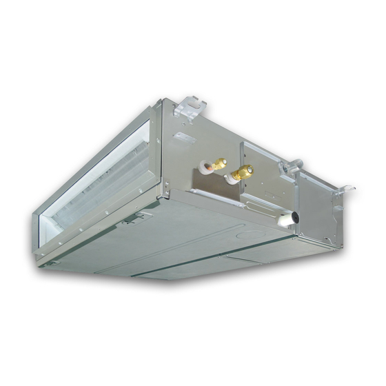
- Page 1 AIR CONDITIONER (SPLIT TYPE) Installation Manual Indoor Unit For commercial use Model name: Concealed Duct Type RAV-GM901BTP-E English...
-
Page 2: Table Of Contents
• The qualified installer is a person who installs, maintains, relocates and removes the air conditioners made by Toshiba Carrier Corporation. He or she has been trained to install, maintain, relocate and remove the air conditioners made by Toshiba Carrier Corporation or, alternatively, he or she has been instructed in such... - Page 3 Warning indications on the air conditioner unit Definition of Protective Gear When the air conditioner is to be transported, installed, maintained, repaired or removed, wear protective gloves and “safety” work clothing. Warning indication Description In addition to such normal protective gear, wear the protective gear described below when undertaking the special work detailed in the following table.
-
Page 4: Precautions For Safety
– 3 – • Wear protective gloves and safety work clothing during Precautions for safety installation, servicing and removal. The manufacturer shall not assume any liability for the damage • Do not touch the aluminum fi n of the outdoor unit. You may caused by not observing the description of this manual. - Page 5 Selection of installation location Installation • When the indoor unit is to be suspended, the designated hanging • When the air conditioner is installed in a small room, provide bolts (M10 or W3/8) and nuts (M10 or W3/8) must be used. appropriate measures to ensure that the concentration of •...
- Page 6 – 5 – • Under no circumstances the power wire must not be extended. • When the air conditioner has been installed or relocated, follow the instructions in the Installation Manual and purge Connection trouble in the places where the wire is extended the air completely so that no gases other than the refrigerant may give rise to smoking and/or a fire.
- Page 7 Explanations given to user CAUTION • Upon completion of the installation work, tell the user where the This Air Conditioner has adopted a refrigerant HFC (R32) circuit breaker is located. If the user does not know where the which does not destroy the ozone layer. circuit breaker is, he or she will not be able to turn it off in the •...
-
Page 8: Accessory Parts
– 7 – Accessory parts Selection of installation place Accessory parts Avoid installing in the following places Select a location for the indoor unit where the cool or warm air will circulate evenly. Avoid installation in the following kinds of locations. Part name Q’ty Shape... -
Page 9: Installation
In the above cases, additionally attach the heat insulator to all positions of the air conditioner, which come to Installation contact with the high-humidity atmosphere. In this case, arrange the side plate (Check port) so that it is easily removed. Apply also a sufficient heat insulation to the duct and connecting part of the duct. - Page 10 – 9 – Installation of hanging bolt Installation of indoor unit Mounting fi lter rails and fi lters Consider the piping / wiring after the unit is hung to Treatment of ceiling Mount the fi lter rail so that the hooks fi t into the corresponding holes. determine the location of the indoor unit installation The ceiling differs according to structure of building.
-
Page 11: Drain Piping
Gravitational drainage Drain piping Reattach the drain cap. CAUTION * For gravitational drainage, remove the white connector (CN504) on the upper left of the circuit board in the Following the Installation Manual, perform the drain piping work so that water is properly drained. Apply a Upper pipe electrical control box. - Page 12 – 11 – Check the draining Heat insulating process As shown in the figure, cover the flexible hose and hose band with the attached heat insulator up to the bottom In the test run, check that water drain is properly performed and water does not leak from the connecting part of the pipes.
- Page 13 Fan characteristics 901BTP Standard air volume: 1700 m Lower limit of external static pressure (120 Pa) Upper limit of external static pressure (120 Pa) High tap (120 Pa) High tap (100 Pa) High tap (80 Pa) Low tap (120 Pa) High tap (65 Pa) High tap...
-
Page 14: Duct Design
– 13 – Duct design Arrangement (Unit: mm) Referring to the following dimensions, manufacture duct at the local site. GM90 <Under air intake> 1359.4 37.5 37.5 <Back air intake> 1360 37.5 37.5 1375 25-EN 26-EN... -
Page 15: Refrigerant Piping
Evacuation Refrigerant piping CAUTION Perform vacuuming from the charge port of valve of Do not scratch the inner surface of the flared part Connecting refrigerant piping the outdoor unit by using a vacuum pump. when removing burrs. CAUTION For details, follow to the Installation Manual attached Flare processing under the condition of scratches to the outdoor unit. -
Page 16: Electrical Connection
– 15 – Heat insulation process Electrical connection Apply heat insulation for the pipes separately at liquid side and gas side. For the heat insulation to the pipes at gas side, be sure to use the material with heat-resisting temperature 120°C or higher. - Page 17 Wiring between indoor unit and outdoor unit Wire connection 1. Figure below shows the wiring connections between the indoor and outdoor units and between the indoor units REQUIREMENT and remote controller. The wires indicated by the broken lines or dot-and-dash lines are provided at the locally. 2.
-
Page 18: Applicable Controls
– 17 – External static pressure Applicable controls Each time button is pushed, indoor settings unit numbers in the control group change cyclically. Select the indoor unit to change Basic procedure for changing REQUIREMENT settings for. Set up a tap change based upon the external static settings When you use this air conditioner for the first The fan of the selected unit runs and the louvers... - Page 19 Power saving mode External static pressure Filter sign setting When using the wireless remote controller Performing settings of the power saving According to the installation condition, the filter sign To set up the external static pressure, use the DIP switch on the circuit board of the wireless reception part. term (Notification of filter cleaning) can be changed.
- Page 20 – 19 – Remote controller switch Group control Push button to return to the normal monitoring function display. Simultaneous twin, triple or double twin system A combination with an outdoor unit allows simultaneous ON/OFF operation of the indoor units. The following Indoor unit data This function is available to call the service monitor system patterns are available.
- Page 21 Group control for system of multiple units [Procedure example] One remote controller can control maximum 8 indoor units as a group. Manual address setup procedure 1. Specify CODE No. [12] with TEMP. While the operation stops, change the setup. buttons. Group control in single system (Stop the operation of the unit.) (CODE No.
- Page 22 – 21 – To recognize the position of the After check of the changed contents, push After confirmation, push button to return corresponding indoor unit though the button. (Setup is determined.) When to the normal mode. 1. Specify CODE No. [14] TEMP. buttons.
-
Page 23: Test Run
8°C Operation Test run Pre-heating operation can be set for cold regions Before test run Wired remote controller where room temperature drops to below zero. Push buttons simultaneously Before turning on the power supply, carry out the 2, 4 for 4 seconds or more when the air following procedure. -
Page 24: Maintenance
– 23 – When a test run is not Wired remote controller Maintenance performed properly When TEMPORARY button is pushed for 10 <Daily maintenance> seconds or more, “Pi!” sound is heard and the When a test run is not performed properly, refer operation changes to test run. -
Page 25: Troubleshooting
Periodic Maintenance Troubleshooting For environmental conservation, it is strongly recommended that the indoor and outdoor units of the air conditioner in use be cleaned and maintained regularly to ensure efficient operation of the air conditioner. Confi rmation and check Confirmation of error log When the air conditioner is operated for a long time, periodic maintenance (once a year) is recommended. - Page 26 – 25 – Error codes and parts to be checked Wired Wireless remote remote controller Sensor block controller display of receiving unit Judging display Wired Main problem parts Parts to be checked / error description conditioner Wireless remote device remote status Operation Timer controller Sensor block...
- Page 27 Wired Wireless remote remote controller Sensor block controller display of receiving unit Judging display Main problem parts Parts to be checked / error description conditioner device status Operation Timer Indication Ready Flashing GR GR OR Abnormal temperature was detected by the temp, Heat sink overheat Outdoor Entire stop...
-
Page 28: Appendix
– 27 – Appendix Work instructions 5. When a commercially available dryer is attached to Existing pipes: Cannot be used. the existing pipes. Are there scratches or dents on the existing pipes? The existing R22 and R410A piping can be reused for Use new pipes. - Page 29 – – 55-EN 56-EN...
- Page 30 144 / 9 Moo 5, Bangkadi Industrial Park, Tivanon Road, Tambol Bangkadi, Amphur Muang, Pathumthani 12000, Thailand 1116950190...
Need help?
Do you have a question about the RAV-GM901BTP-E and is the answer not in the manual?
Questions and answers