Table of Contents
Advertisement
Quick Links
Advertisement
Table of Contents

Related Manuals for Zte ZXSDR R8872A


Summary of Contents for Zte ZXSDR R8872A
- Page 1 ZXSDR R8872A Macro Remote Radio Unit Hardware Description Hardware Version: HV1.0 ZTE CORPORATION No. 55, Hi-tech Road South, ShenZhen, P.R.China Postcode: 518057 Tel: +86-755-26771900 Fax: +86-755-26770801 URL: http://support.zte.com.cn E-mail: support@zte.com.cn...
- Page 2 ZTE CORPORATION is prohibited. Additionally, the contents of this document are protected by contractual confidentiality obligations. All company, brand and product names are trade or service marks, or registered trade or service marks, of ZTE CORPORATION or of their respective owners.
-
Page 3: Table Of Contents
Chapter 2 External Cables ................. 2-1 2.1 Grounding Cable ....................2-1 2.2 DC Power Cable ....................2-1 2.3 Optical Fiber ...................... 2-2 2.4 Antenna Feeder Jumper ..................2-3 2.5 AISG/MON Interface Cable ................. 2-3 Glossary ......................I SJ-20141127113509-002|2014-11-17 (R1.0) ZTE Proprietary and Confidential... - Page 4 This page intentionally left blank. SJ-20141127113509-002|2014-11-17 (R1.0) ZTE Proprietary and Confidential...
-
Page 5: About This Manual
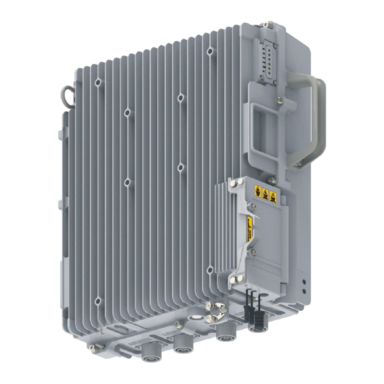
About This Manual Purpose This manual describes the external view and external cables of the ZXSDR R8872A. Intended Audience This manual is intended for: On-site installation engineers Maintenance engineers What Is in This Manual This manual contains the following chapters. - Page 6 This page intentionally left blank. SJ-20141127113509-002|2014-11-17 (R1.0) ZTE Proprietary and Confidential...
- Page 7 3. Chassis bottom (with interfaces) interfaces) Table of Contents External Interfaces .....................1-1 Indicators ........................1-3 1.1 External Interfaces Interfaces at the Bottom of the ZXSDR R8872A Figure 1-2 shows the interfaces at the bottom of the ZXSDR R8872A. SJ-20141127113509-002|2014-11-17 (R1.0) ZTE Proprietary and Confidential...
- Page 8 ZXSDR R8872A Hardware Description Figure 1-2 Interfaces at the Bottom For a description of the interfaces at the bottom, refer to Table 1-1. Table 1-1 Description of Interfaces at the Bottom Silk Screen Interface Interface Type or Connector AISG /MON...
-
Page 9: Chapter 1 External View
Power input interface Customized connector AC grounding terminal 1.2 Indicators Panel indicators of the ZXSDR R8872A are located in the upper part of the chassis side, Figure 1-4. They indicate the operational status of the RRU. SJ-20141127113509-002|2014-11-17 (R1.0) ZTE Proprietary and Confidential... - Page 10 Silk Meaning Color Description Screen Operation Green Steady on: The ZXSDR R8872A is being restarted or indicator powered on. Flash (1 Hz): The ZXSDR R8872A is operating prop- erly. Flashing (5 Hz): The ZXSDR R8872A is downloading versions. Steady off: Self-test fails.
- Page 11 Steady on in green: The link between the RRU and the status BBU is normal, and the cell is created successfully. indicator Steady on in red: The link between the RRU and the BBU is abnormal, and the cell fails to be created. SJ-20141127113509-002|2014-11-17 (R1.0) ZTE Proprietary and Confidential...
- Page 12 ZXSDR R8872A Hardware Description This page intentionally left blank. SJ-20141127113509-002|2014-11-17 (R1.0) ZTE Proprietary and Confidential...
-
Page 13: Chapter 2 External Cables
2.2 DC Power Cable Purpose The DC power cable leads external DC power supplies into the ZXSDR R8872A. External View Figure 2-2 shows a DC power cable at one end of the ZXSDR R8872A. -
Page 14: Optical Fiber
Black Connection One end of the DC power cable is connected to the DC power supply interface inside the maintenance cavity of the ZXSDR R8872A, and the other end is connected to an external power supply device. 2.3 Optical Fiber Purpose The optical fiber connects the ZXSDR R8872A to the BBU or cascade RRUs. -
Page 15: Antenna Feeder Jumper
Connection One end of the antenna feeder jumper is connected to an antenna interface (ANT1 to ANT4) on the ZXSDR R8872A, and the other end is connected to the interface that the main feeder corresponds to. 2.5 AISG/MON Interface Cable... - Page 16 ZXSDR R8872A Hardware Description This page intentionally left blank. SJ-20141127113509-002|2014-11-17 (R1.0) ZTE Proprietary and Confidential...
-
Page 17: Glossary
Glossary AISG - Antenna Interface Standards Group - Base Band Unit - Local Maintenance Terminal NSBT - NodeB-Side Smart Bias Tee - Remote Radio Unit VSWR - Voltage Standing Wave Ratio SJ-20141127113509-002|2014-11-17 (R1.0) ZTE Proprietary and Confidential...
Need help?
Do you have a question about the ZXSDR R8872A and is the answer not in the manual?
Questions and answers