Advertisement
Quick Links
GB
Contents
1
INTRODUCTION ________________________________________________ 9
2
TECHNICAL SPECIFICATIONS ____________________________________ 9
3
SETTING UP THE TABLE ________________________________________ 10
3.1
PACKING LIST __________________________________________________ 10
3.2
INNER TABLE ASSEMBLY DIAGRAM _______________________________ 11
3.3
MAIN TABLE ASSEMBLY DIAGRAM ________________________________ 12
3.4
COMPLETED ANTI VIBRATION TABLE ______________________________ 13
4
MAINTENANCE ________________________________________________ 13
8
KERN YPS-01
Version 1.0 7/2006
Installation Information
Anti-Vibration table
YPS-IA-defsi-0610
Advertisement

Summary of Contents for KERN YPS-01
-
Page 1: Table Of Contents
KERN YPS-01 Version 1.0 7/2006 Installation Information Anti-Vibration table Contents INTRODUCTION ________________________________________________ 9 TECHNICAL SPECIFICATIONS ____________________________________ 9 SETTING UP THE TABLE ________________________________________ 10 PACKING LIST __________________________________________________ 10 INNER TABLE ASSEMBLY DIAGRAM _______________________________ 11 MAIN TABLE ASSEMBLY DIAGRAM ________________________________ 12 COMPLETED ANTI VIBRATION TABLE ______________________________ 13... -
Page 2: Introduction
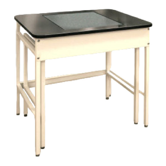
1 INTRODUCTION The KERN Anti-Vibration Table is designed for use in the laboratory or metrology room to provide suitable working conditions for devices that are sensitive to vibrations and shocks. The table comprises two separate parts- • An internal working surface consisting of a large marble slab mounted on rubber shock absorbing mounts •... -
Page 3: Setting Up The Table
3 SETTING UP THE TABLE 3.1 PACKING LIST NAME (ASSEMBLY DIAGRAM) MARBLE RUBBER INNER TABLE RAIL(SMALL) M8×16 SCREW INNER TABLE MAIN TABLE MARBLE SUPPORT RAIL INNER TABLE SIDE ASSEMBLY(SMALL) ADJUSTABLE FOOT FRONT TRIM PANEL Z-CLIP M8×8 SCREW TABLE TOP MAIN TABLE RAIL (LARGE) MAIN TABLE SIDE ASSEMBLY(LARGE) HEXAGON SPANNER YPS-IA-defsi-0610... -
Page 4: Inner Table Assembly Diagram
3.2 INNER TABLE ASSEMBLY DIAGRAM Assembly instructions: 1. Assemble the 3 x INNER TABLE RAILS using the HEXAGON SPAN- NER with twelve M8 x 16 screws onto the 2 x INNER TABLE SIDE ASSEMBLIES. Pay attention that the rails are assembled with the ho- les facing downwards. -
Page 5: Main Table Assembly Diagram
3.3 MAIN TABLE ASSEMBLY DIAGRAM Assembly instructions: 1. Assemble the FRONT TRIM PANEL using four M8 x 16 screws onto the 2 x MAIN TABLE SIDE ASSEMBLIES. 2. Fix the 2 x TABLE RAILS using eight M8 x 16 screws onto the MAIN TABLE SIDE ASSEMBLIES. -
Page 6: Completed Anti Vibration Table
3.4 COMPLETED ANTI VIBRATION TABLE 4 MAINTENANCE • Do not dismantle the Anti-Vibration table without following the assembly instructions. • Do not move the Anti-Vibration Table violently and abruptly. It is recommended to move and put down the Table gently. •...